Cisco 7604 Processor Guide - Page 43
Color, Description, SYSTEM, CONSOLE, PWR MGMT, SWITCH LOAD, PCMCIA
 |
View all Cisco 7604 manuals
Add to My Manuals
Save this manual to your list of manuals |
Page 43 highlights
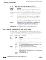
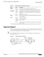
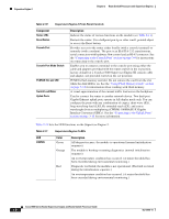
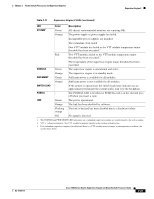
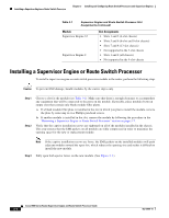
Chapter 2 Route Switch Processors and Supervisor Engines Supervisor Engine 2 Table 2-11 Supervisor Engine 2 LEDs (continued) LED SYSTEM1 Color Green Description All chassis environmental monitors are reporting OK. Orange The power supply or power supply fan failed. Incompatible power supplies are installed. The redundant clock failed. One VTT2 module has failed or the VTT module temperature minor threshold has been exceeded.3 Red Two VTT modules failed or the VTT module temperature major threshold has been exceeded.3 The temperature of the supervisor engine major threshold has been exceeded. CONSOLE Green The supervisor engine is operational and active. PWR MGMT1 Orange Green The supervisor engine is in standby mode. Sufficient power is available for all modules. SWITCH LOAD Orange - Sufficient power is not available for all modules. If the system is operational, the switch load meter indicates (as an approximate percentage) the current traffic load over the backplane. PCMCIA LINK Green The PCMCIA LED is lit when no PCMCIA card is in the slot and goes off when you insert a card. The port is operational. Orange The link has been disabled by software. Flashing The link is bad and has been disabled due to a hardware failure. orange Off No signal is detected. 1. The SYSTEM and PWR MGMT LED indications on a redundant supervisor engine are synchronized to the active engine. 2. VTT = voltage termination. The VTT module terminates signals on the system switching bus. 3. If no redundant supervisor engine is installed and there is a VTT module minor or major overtemperature condition, the system shuts down. OL-10100-11 Cisco 7600 Series Router Supervisor Engine and Route Switch Processor Guide 2-25
-
 1
1 -
2
-
3
-
4
-
5
-
6
-
7
-
8
-
9
-
10
-
11
-
12
-
13
-
14
-
15
-
16
-
17
-
18
-
19
-
20
-
21
-
22
-
23
-
24
-
25
-
26
-
27
-
28
-
29
-
30
-
31
-
32
-
33
-
34
-
35
-
36
-
37
-
 38
38 -
 39
39 -
 40
40 -
 41
41 -
 42
42 -
 43
43 -
 44
44 -
 45
45 -
 46
46 -
 47
47 -
 48
48 -
49
-
50
-
51
-
52
-
53
-
54
-
55
-
56
-
57
-
58
-
59
-
60
-
61
-
62
-
63
-
64
-
65
-
66
-
67
-
68
-
69
-
70
-
71
-
72
-
73
-
74
-
75
-
76
-
77
-
78
-
79
-
80
-
81
-
82
-
83
-
84
-
85
-
86
-
87
-
88
-
89
-
90
-
91
-
92
-
93
-
94
-
95
-
96
-
97
-
98
 |
 |