Cisco 7609-S User Guide - Page 12
Cisco 7600 Series Router Installation Guide - series routers
 |
View all Cisco 7609-S manuals
Add to My Manuals
Save this manual to your list of manuals |
Page 12 highlights
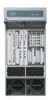
rack using the procedures contained in Cisco 7600 Series Router Installation Guide. If your Cisco 7606-S chassis is already rack-mounted, proceed to step 2. 2. Open the FIPS kit packaging (part number CVPN7600FIPS/KIT=). The kit contains the following items: • An opacity shield assembly for the Cisco 7606-S router (part number 800-26211). The opacity shield part number is located on the outside of the protective packaging. • A bag containing the installation hardware (In some kits there is no bag; the installation hardware is premounted in the opacity shield. • An envelope with 30 FIPS tamper evidence labels and a disposable ESD wrist strap. 3. Remove the opacity shield from its protective packaging. • If the thumbscrews and the snap rivet fasteners are already installed on the opacity shield, remove the four snap rivet fasteners from the opacity shield; leave the thumbscrews installed. Proceed to step 5. Note: Verify that the thumbscrews are started only two or three turns in the opacity shield. • If the opacity shield comes with a bag of installation hardware (69-1483), open the bag and remove the two thumbscrews and four snap rivet fasteners. The snap rivet fasteners come assembled; you need to separate the two pieces of the snap rivet fastener by removing the snap rivet pin from the snap rivet sleeve before you install them. Proceed to step 4. Note: Extra snap rivet fasteners are included in the bag of installation hardware in case of loss or damage. • Start the two thumbscrews in the corresponding threaded holes in the opacity shield (see Figure 5); two or three turns is sufficient. Do not thread the thumbscrews too far into the opacity shield. • Open the envelope containing the disposable ESD wrist strap. Attach the disposable ESD wrist strap to your wrist. Attach the other end of the wrist strap to exposed metal on the chassis. • Position the opacity shield over the air intake side of the chassis so that the two thumbscrews on the opacity shield are aligned with the unused L-bracket screw holes on the chassis. • Press the opacity shield firmly against the side of the chassis and secure the opacity shield to the chassis with the two thumbscrews. 4. Position the rivet sleeve over one of the square cutouts on the opacity shield. Refer to Figure 5 for snap rivet fastener placement. Press the rivet sleeve through the cutout, through the opacity shield material, and through one of the chassis air vent perforations. Note: You might need to try different cutouts to find the one cutout that aligns correctly with a chassis air vent perforation. 5. Push the rivet pin through the rivet sleeve until you hear a click. Note: If you do not hear a click, remove and inspect the snap rivet fastener. If the rivet sleeve appears expanded or damaged, discard the snap rivet fastener and use a new one from the extras supplied in the bag of fasteners. 6. Repeat step 4 and step 5 for the remaining three snap rivet fasteners. © Copyright 2011 Cisco Systems, Inc. 12 This document may be freely reproduced and distributed whole and intact including this Copyright Notice.
-
 1
1 -
2
-
3
-
4
-
5
-
6
-
 7
7 -
 8
8 -
 9
9 -
 10
10 -
 11
11 -
 12
12 -
 13
13 -
 14
14 -
 15
15 -
 16
16 -
 17
17 -
18
-
19
-
20
-
21
-
22
 |
 |
