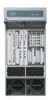
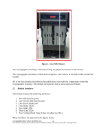
Cisco 7609-S User Guide - Page 8
Router Physical Interface, FIPS 140-2 Logical Interface - power
 |
View all Cisco 7609-S manuals
Add to My Manuals
Save this manual to your list of manuals |
Page 8 highlights
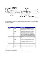
PWR MGMT Orange Green Orange Red DISK 0 and N/A DISK 1 Power-up mode; running self-diagnostics. Power management is functioning normally and sufficient power is available for all modules. A minor power management problem has been detected. There is insufficient power for all modules to power up. A major power failure has occurred. These LEDs are illuminated green when the installed Flash PC card is being accessed and is performing either a read operation or a write operation. Table 2 - LED Indicators The module provides a number of physical and logical interfaces to the device, and the physical interfaces provided by the module are mapped to the following FIPS 140-2 defined logical interfaces: data input, data output, control input, status output, and power. The logical interfaces and their mapping are described in the following table: Router Physical Interface Gigabit/SFP Ethernet ports Console Port Gigabit/SFP Ethernet ports Console Port Gigabit/SFP Ethernet ports Console Port Gigabit/SFP Ethernet ports Console Port LEDs Power plug FIPS 140-2 Logical Interface Data Input Interface Data Output Interface Control Input Interface Status Output Interface Power Interface Table 3 - FIPS 140-2 Logical Interfaces 2.3 Roles and Services Authentication in the module is identity-based. There are two main roles in the router that operators can assume: 1. the Crypto Officer role and 2. the User role. The administrators of the router assumes the Crypto Officer role in order to configure and maintain the router using Crypto Officer services, while the Users exercise only the basic User services. A detailed list of services attributed to each role can be found in section 2.3.2 © Copyright 2011 Cisco Systems, Inc. 8 This document may be freely reproduced and distributed whole and intact including this Copyright Notice.
-
 1
1 -
2
-
 3
3 -
 4
4 -
 5
5 -
 6
6 -
 7
7 -
 8
8 -
 9
9 -
 10
10 -
 11
11 -
 12
12 -
 13
13 -
14
-
15
-
16
-
17
-
18
-
19
-
20
-
21
-
22
 |
 |
