Cisco 8-10GBE-RF Hardware Installation Guide - Page 18
Back Panels - switch
 |
View all Cisco 8-10GBE-RF manuals
Add to My Manuals
Save this manual to your list of manuals |
Page 18 highlights
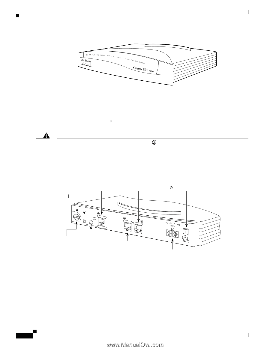
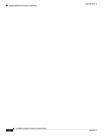
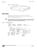
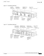
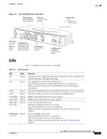
Back Panels Figure 1-3 Cisco 804 IDSL Front Panel IDSL ETHERNET IDSL Chapter 1 Overview 30770 Back Panels The figures in this section show the back panel of each of the Cisco 800 series routers. If the symbol of suitability ( ) appears above a port, you can connect the port directly to a public network that follows the European Union standards. Warning If the symbol of suitability with an overlaid cross ( ) appears above a port, you must not connect the port to a public network that follows the European Union standards. Connecting the port to this type of public network can cause severe injury or damage your router. Figure 1-4 Cisco 801 Router Back Panel Link LED Indicates state of Ethernet port. On when connected. Ethernet port Connect Ethernet network device. ISDN BRI S/T port Connect to external NT1 or ISDN wall jack. Power switch l = On. = Standby or no power output. 11666 LINK HUB NO HUB ETHERNET 10 BASE T Cisco 801 CONSOLE ISDN S/T Cable lock Use cable lock to physically secure router. HUB/NO HUB button (for Ethernet port) Console port Determines cable Connect PC or type for Ethernet terminal. device connection. Locking power connector Connect power supply. Cisco 800 Series Routers Hardware Installation Guide 1-4 78-5373-04
-
 1
1 -
2
-
3
-
4
-
5
-
6
-
7
-
8
-
9
-
10
-
11
-
12
-
 13
13 -
 14
14 -
 15
15 -
 16
16 -
 17
17 -
 18
18 -
 19
19 -
 20
20 -
 21
21 -
 22
22 -
 23
23 -
24
-
25
-
26
-
27
-
28
-
29
-
30
-
31
-
32
-
33
-
34
-
35
-
36
-
37
-
38
-
39
-
40
-
41
-
42
-
43
-
44
-
45
-
46
-
47
-
48
-
49
-
50
-
51
-
52
-
53
-
54
-
55
-
56
-
57
-
58
-
59
-
60
-
61
-
62
-
63
-
64
-
65
-
66
-
67
-
68
-
69
-
70
 |
 |