Cisco ASR1006-10G-SEC/K9 Installation Guide - Page 11
Attaching the Chassis Rack-Mount Brackets, Chassis Front Rack-Mount Brackets
 |
View all Cisco ASR1006-10G-SEC/K9 manuals
Add to My Manuals
Save this manual to your list of manuals |
Page 11 highlights
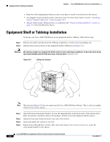
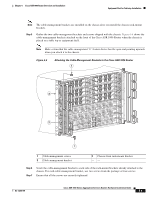
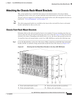
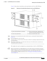
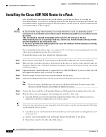
Chapter 6 Cisco ASR 1006 Router Overview and Installation Attaching the Chassis Rack-Mount Brackets Attaching the Chassis Rack-Mount Brackets This section explains how to attach the front and rear rack-mount brackets to the chassis. Before installing the chassis in the rack, you must install the rack-mount brackets on each side of the chassis. The parts and tools required for installing the rack-mount brackets and cable-management brackets are listed in the "Tools and Equipment" section on page 5-23. Note The cable-management brackets are installed on the chassis after you install the chassis rack-mount brackets and mount the chassis in the rack. Chassis Front Rack-Mount Brackets Determine where in the rack you want the chassis to be mounted. If you are mounting more than one chassis in the rack, then start from the bottom up or the center of the rack. Figure 6-8 shows the brackets attached to the chassis. Depending on the bracket holes you use, the chassis may protrude in the rack. To install the front rack-mount brackets on the Cisco ASR 1006 Router, perform the following steps: Step 1 Locate the threaded holes on the side of the chassis. Make certain that you hold the front rack-mount bracket with the ear and holes facing outward and towards the front of the chassis (see Figure 6-8). Figure 6-8 Attaching the Front Rack-Mount Brackets to the Cisco ASR 1006 Router A/L C/A A/L C/A A/L C/A 0 3 A/L C/A OL-13208-09 1 2 A/L C/A A/L C/A 0 1 A/L C/A A/L C/A 0 1 1 A/L C/A A/L C/A 0 1 A/L C/A A/L C/A 0 1 0 A/L C/A A/L C/A 0 1 PWR ACTV F1 STAT STBY ASR1000-ESP10 F0 PWR ACTV STAT STBY ASR1000-ESP10 R1 PWR ACTV STAT STBY ASR1000-RP1 CRIT MAJ MIN R0 PWR ACTV STAT STBY ASR1000-RP1 CRIT MAJ MIN ACO ACO HD USB 0 BF 1 DISK HD USB 0 BF 1 DISK 2 2 2 2 2 2 A/L C/A A/L C/A A/L C/A A/L C/A A/L C/A 3 A/L C/A 3 A/L C/A 3 A/L C/A 3 A/L C/A 3 A/L C/A A/L C/A 0 1 A/L C/A 0 1 A/L C/A SPA-4XOC3-POS SPA-4XOC3-POS SPA-4XOC3-POS SPA-4XOC3-POS SPA-4XOC3-POS SPA-4XOC3-POS STATUS STATUS STATUS STATUS STATUS STATUS ASR1000-SIP10 PWR STATUS ASR1000-SIP10 PWR STATUS ASR1000-SIP10 PWR STATUS 0 1 A/L C/A 0 1 A/L C/A 0 1 A/L C/A 0 1 CARRIER LINK BITS MGMT ETHERNET CARRIER LINK BITS MGMT ETHERNET CON AUX CON AUX A/L C/A A/L C/A A/L C/A A/L C/A A/L C/A A/L C/A 2 2 2 2 2 2 A/L C/A A/L C/A A/L C/A A/L C/A A/L C/A A/L C/A 3 A/L C/A 3 A/L C/A 3 A/L C/A 3 A/L C/A 3 A/L C/A 3 A/L C/A Cisco ASR 1006 SPA-4XOC3-POS STATUS STATUS SPA-4XOC3-POS 2 STATUS SPA-4XOC3-POS STATUS SPA-4XOC3-POS 1 STATUS SPA-4XOC3-POS SPA-4XOC3-POS STATUS 0 F1 F0 R1 R0 280035 1 Front rack-mount bracket screws 2 Front rack-mount bracket 4 32 1 3 Front rack-mount bracket ear and holes 4 Chassis side vent location Cisco ASR 1000 Series Aggregation Services Routers Hardware Installation Guide 6-11
-
 1
1 -
2
-
3
-
4
-
5
-
 6
6 -
 7
7 -
 8
8 -
 9
9 -
 10
10 -
 11
11 -
 12
12 -
 13
13 -
 14
14 -
 15
15 -
 16
16 -
17
-
18
-
19
-
20
-
21
-
22
-
23
-
24
-
25
-
26
-
27
-
28
-
29
-
30
-
31
-
32
-
33
-
34
-
35
-
36
 |
 |