Cisco CISCO2851 User Guide - Page 3
The Cisco 2851 Cryptographic Module Physical Characteristics - router
 |
View all Cisco CISCO2851 manuals
Add to My Manuals
Save this manual to your list of manuals |
Page 3 highlights
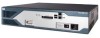
Cisco 2851 Routers The Cisco 2851 Cryptographic Module Physical Characteristics Figure 1 The Cisco 2851 router case Figure 2 SYS PWR AUX/ PWR SYS ACT CF OPTIONAL RPS INPUT COMPACT FLASH 1 Do Not Remove During Network Operation 0 12V -48V 11A 4A CONSOLE AUX 100-240 50/60 V~ Hz 4A 95903 The Cisco 2851 router is a multiple-chip standalone cryptographic module. The router has a processing speed of 450MHz. Depending on configuration, either the internal Safenet chip or the IOS software is used for cryptographic operations. The cryptographic boundary of the module is the device's case, shown in Figure 1. All of the functionality discussed in this document is provided by components within this cryptographic boundary. The interface for the router is located on the front and rear panels as shown in Figure 2 and Figure 3. Cisco 2851 Front Panel Physical Interfaces 7 6 5 43 2 1 OPTIONAL RPS INPUT 12V 18A SYS AUX/ SYS 1 PWR PWR ACT CF COMPACT FLASH 0 Do Not Remove During Network Operation CONSOLE AUX 100-240 V~ 3A 50/60 Hz 95553 OL-8717-01 Cisco 2851 Integrated Services Router FIPS 140-2 Non Proprietary Security Policy 3
-
 1
1 -
 2
2 -
 3
3 -
 4
4 -
 5
5 -
 6
6 -
 7
7 -
 8
8 -
 9
9 -
10
-
11
-
12
-
13
-
14
-
15
-
16
-
17
-
18
-
19
-
20
-
21
-
22
-
23
-
24
 |
 |
