Cisco CISCO813-RF Hardware Installation Guide - Page 30
Connecting Hubs,
 |
View all Cisco CISCO813-RF manuals
Add to My Manuals
Save this manual to your list of manuals |
Page 30 highlights
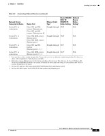
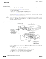
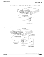
Installing Your Router Chapter 2 Installation Connecting Hubs If you have a Cisco 803, 804, or 804 IDSL router, you can connect as many as four hubs. Before connecting a hub, see Table 2-2, and do the following: • Choose Ethernet cables. • On the router, set the HUB/NO HUB or TO HUB/TO PC button. • On the hub, set the HUB/NO HUB button or its equivalent. Follow the steps in Figure 2-1 to connect a hub to a Cisco 800 series ISDN or IDSL router. This figure shows a Cisco 803 router with four Ethernet ports. Caution Always connect the yellow cable or an Ethernet cable to the yellow ports on the router. Do not connect the cable to an ISDN S/T or U port, to an IDSL port, or to an NT1. Connecting the cable to the wrong port or NT1 can damage your router. Figure 2-1 Connecting a Hub 1. Set HUB/NO HUB or TO HUB/TO PC button. Cisco 803 router 2. Connect cable to: • Yellow Ethernet port on Cisco 801, 802 or 802 IDSL router. • Any yellow Ethernet port on Cisco 803, 804, or 804 IDSL router. HUB NO HUB ETHERNET 10 BASE T 0 1 2 3 Cisco 803 CONSOLE ISDN S/T PHONE 1 2 Cisco Micro Hub 10/100 11674 1X 101S00PBBEaasEseeDTTX LED SOLID BLINK 1 5 2 6 3 7 4 8 2X ETHERNET 3X 4X 6X 7X 8X MDI MDI-X 3. Connect other end of cable to hub. 4. If applicable, check setting of hub equivalent of router HUB/NO HUB button. To verify your hub connection, verify that one of the following LEDs is on after you have completed the router installation: • LINK LED on the Cisco 801, 802, or 802 IDSL back panel. • LKØ, LK1, LK2, or LK3 LED on the Cisco 803 or Cisco 804 front panel. • ETHERNET 1, 2, 3, or 4 LED on the Cisco 804 IDSL front panel. If the LED is not on, see Table 3-2 in Chapter 3, "Troubleshooting." Cisco 800 Series Routers Hardware Installation Guide 2-8 78-5373-04
-
 1
1 -
2
-
3
-
4
-
5
-
6
-
7
-
8
-
9
-
10
-
11
-
12
-
13
-
14
-
15
-
16
-
17
-
18
-
19
-
20
-
21
-
22
-
23
-
24
-
 25
25 -
 26
26 -
 27
27 -
 28
28 -
 29
29 -
 30
30 -
 31
31 -
 32
32 -
 33
33 -
 34
34 -
 35
35 -
36
-
37
-
38
-
39
-
40
-
41
-
42
-
43
-
44
-
45
-
46
-
47
-
48
-
49
-
50
-
51
-
52
-
53
-
54
-
55
-
56
-
57
-
58
-
59
-
60
-
61
-
62
-
63
-
64
-
65
-
66
-
67
-
68
-
69
-
70
 |
 |
