Cisco G1 Installation Guide - Page 12
Disconnecting Power from a Cisco 7200 VXR Router DC-Input Power Supply, Warning, Step 1
 |
UPC - 746320679488
View all Cisco G1 manuals
Add to My Manuals
Save this manual to your list of manuals |
Page 12 highlights
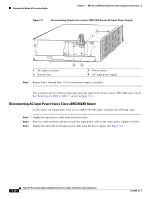
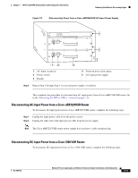
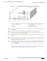
Removing the Network Processing Engine Chapter 7 NPE-G1 and NPE-G2 Installation and Configuration Information Warning Before completing any of the following steps, and to prevent short-circuit or shock hazards, ensure that power is removed from the DC circuit. To ensure that all power is OFF, locate the circuit breaker on the panel board that services the DC circuit, switch the circuit breaker to the OFF position, and tape the switch handle of the circuit breaker in the OFF position. Statement 332 Warning When you install the unit, the ground connection must always be made first and disconnected last. Statement 42 Step 1 Step 2 Step 3 At the rear of the router, check that the power switch on the power supply is in the off (O) position. (For the Cisco 7200 VXR routers, see Figure 7-3.) Ensure that no current is running through the -V and +V leads. To ensure that all power is off, locate the circuit breaker on the panel board that services the DC circuit, switch the circuit breaker to the off position, and tape the switch handle of the circuit breaker in the off position. Disconnect the -V and +V leads. You can leave the ground cable connected. For a Cisco 7200 VXR router, remove the cable tie that secures the -V, +V, and ground leads to the power supply faceplate. Save the cable tie. Note The cable tie that accompanied your Cisco 7200 VXR router DC-input power supply can be removed and replaced on the power supply without the use of a tool. If you secured the DC-input power supply leads to the power supply faceplate using a different type of cable tie, use a wire stripper to cut that cable tie from the power supply. Figure 7-3 Disconnecting Power from a Cisco 7200 VXR Router DC-Input Power Supply 1 2 66431 networking xxxx engine 1 DC-input receptacle 2 Internal fans 3 4 3 Power switch 4 DC-input power supply Step 4 Using a 3/16-inch flat-blade screwdriver, loosen the screw below the +V lead receptacle and pull the lead from the connector. See Figure 7-3. 7-12 Network Processing Engine and Network Services Engine Installation and Configuration OL-4448-12
-
 1
1 -
2
-
3
-
4
-
5
-
6
-
 7
7 -
 8
8 -
 9
9 -
 10
10 -
 11
11 -
 12
12 -
 13
13 -
 14
14 -
 15
15 -
 16
16 -
 17
17 -
18
-
19
-
20
-
21
-
22
-
23
-
24
-
25
-
26
-
27
-
28
-
29
-
30
-
31
-
32
-
33
-
34
-
35
-
36
-
37
-
38
-
39
-
40
-
41
-
42
-
43
-
44
-
45
-
46
-
47
-
48
-
49
-
50
-
51
-
52
-
53
-
54
-
55
-
56
-
57
-
58
-
59
-
60
-
61
-
62
-
63
-
64
-
65
-
66
-
67
-
68
 |
 |
