Cisco G1 Installation Guide - Page 45
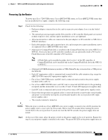
Powering Up the Router, Step 1, Caution
 |
UPC - 746320679488
View all Cisco G1 manuals
Add to My Manuals
Save this manual to your list of manuals |
Page 45 highlights
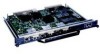
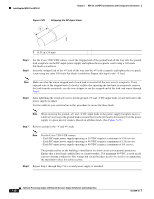
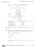
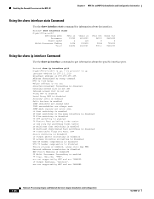
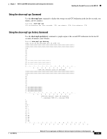
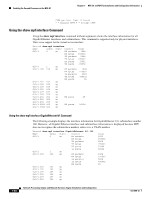
Chapter 7 NPE-G1 and NPE-G2 Installation and Configuration Information Installing the NPE-G1 or NPE-G2 Powering Up the Router To power up a Cisco 7200 VXR router, Cisco uBR7246VXR router, or Cisco uBR7225VXR router that has an installed power supply, complete the following steps: Step 1 Check for the following: - Each port adapter is inserted in its slot, and its respective port adapter lever is in the locked position. - The network processing engine and the I/O controller or I/O controller blank panel are inserted in their respective slots, and the captive installation screws are tightened. - All network interface cables are connected to the port adapters or I/O controller or NPE-G1 or NPE-G2 interfaces. - Each cable interface line card is inserted in its slot, and its respective captive installation screws are tightened (Cisco uBR7246VXR router only). - (Optional) A CompactFlash Disk is installed in the CompactFlash Disk slot in the NPE-G1 or NPE-G2. If you also have an I/O controller installed, you can optionally install a PC Card or Flash Disk in one of the I/O controller's PC Card slots. Note A Flash Disk can be installed in either slot 0 or slot 1 of the I/O controller. A CompactFlash Disk can be installed only in the CompactFlash Disk slot in the NPE-G1 or NPE-G2. - (Optional) A USB Flash memory module or USB eToken Pro key is inserted into a USB port on the NPE-G2. - Each AC-input power cable is connected and secured with the cable-retention clip, except for uBR7224VXR routers(AC-input power supplies only). - For a Cisco 7200 VXR router, each DC lead is connected and secured to the power supply faceplate with a cable tie. - For a Cisco uBR7246VXR router, each DC lead is connected with M4 nuts for the grounding receptacle and the strain-relief cover over the +V and -V leads (DC-input power supplies only). - Each DC lead is connected and secured to the power source (DC-input power supplies only). - Ensure that the tape (that you applied earlier) is removed from the circuit breaker switch handle, and power is restored by moving the circuit breaker handle to the on (|) position (DC-input power supplies only). - The console terminal is turned on. Caution When the power switch on a Cisco uBR7200 series power supply is turned to the off (O) position, the power supply enters a reset cycle for 90 seconds. Wait at least 90 seconds before turning the power switch back to the on (|) position. If you do not wait the full 90 seconds, the power supply does not restart. Step 2 At the rear of the router, place the power switch on the power supply in the on (|) position. Repeat this step if a second power supply is installed in the router. The green OK LED on the power supply turns on. OL-4448-12 Network Processing Engine and Network Services Engine Installation and Configuration 7-45
-
 1
1 -
2
-
3
-
4
-
5
-
6
-
7
-
8
-
9
-
10
-
11
-
12
-
13
-
14
-
15
-
16
-
17
-
18
-
19
-
20
-
21
-
22
-
23
-
24
-
25
-
26
-
27
-
28
-
29
-
30
-
31
-
32
-
33
-
34
-
35
-
36
-
37
-
38
-
39
-
 40
40 -
 41
41 -
 42
42 -
 43
43 -
 44
44 -
 45
45 -
 46
46 -
 47
47 -
 48
48 -
 49
49 -
 50
50 -
51
-
52
-
53
-
54
-
55
-
56
-
57
-
58
-
59
-
60
-
61
-
62
-
63
-
64
-
65
-
66
-
67
-
68
 |
 |
