Cisco IE-3010-16S-8PC Hardware Installation Guide - Page 11
/100 Fast Ethernet Ports, PoE Ports - switch
 |
View all Cisco IE-3010-16S-8PC manuals
Add to My Manuals
Save this manual to your list of manuals |
Page 11 highlights
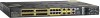
Chapter 1 Product Overview Cable Side The100BASE-FX SFP ports and the 10/100 PoE ports are grouped in pairs. The first member of the pair (port 1) is above the second member (port 2) on the left. Port 3 is above port 4, and so on. The dual-purpose ports are numbered 1 and 2. Figure 1-2 13 Cisco IE-3010-16S-8PC Cable-Side View 5 6 78 9 208363 PO W ER OVER ETHERNET PO W ER OVER ETHERNET C isco IE 3010 2 4 10 1 SD flash memory card slot 2 LEDs 3 Express Setup button 4 100BASE-FX SFP ports 5 10/100 PoE ports 6 Dual purpose ports 7 RJ-45 console port 8 USB (mini-Type B) console port 9 Power-input terminal 10 Alarm port 10/100 Fast Ethernet Ports You can set the 10/100 ports on the switch to operate in any combination of half duplex, full duplex, or 10 or 100 Mb/s. You can set the ports for speed and duplex autonegotiation. The default setting is autonegotiate. When set for autonegotiation, the switch determines the speed and duplex settings of the attached device and advertises its own capabilities. If the connected device also supports autonegotiation, the switch negotiates the best connection (the fastest line speed that both devices support and full-duplex transmission if the attached device supports it) and configures itself accordingly. In all cases, the attached device must be within 328 feet (100 meters). PoE Ports Warning Voltages that present a shock hazard may exist on Power over Ethernet (PoE) circuits if interconnections are made using uninsulated exposed metal contacts, conductors, or terminals. Avoid using such interconnection methods, unless the exposed metal parts are located within a restricted access location and users and service people who are authorized within the restricted access location are made aware of the hazard. A restricted access area can be accessed only through the use of a special tool, lock and key or other means of security. Statement 1072 78-19581-01 Cisco IE 3010 Switch Hardware Installation Guide 1-3
-
 1
1 -
2
-
3
-
4
-
5
-
 6
6 -
 7
7 -
 8
8 -
 9
9 -
 10
10 -
 11
11 -
 12
12 -
 13
13 -
 14
14 -
 15
15 -
 16
16 -
17
-
18
-
19
-
20
-
21
-
22
-
23
-
24
-
25
-
26
-
27
-
28
-
29
-
30
-
31
-
32
-
33
-
34
-
35
-
36
-
37
-
38
-
39
-
40
-
41
-
42
-
43
-
44
-
45
-
46
-
47
-
48
-
49
-
50
-
51
-
52
-
53
-
54
-
55
-
56
-
57
-
58
-
59
-
60
-
61
-
62
-
63
-
64
-
65
-
66
-
67
-
68
-
69
-
70
-
71
-
72
-
73
-
74
-
75
-
76
-
77
-
78
-
79
-
80
-
81
-
82
-
83
-
84
-
85
-
86
-
87
-
88
-
89
-
90
-
91
-
92
-
93
-
94
-
95
-
96
-
97
-
98
 |
 |
