Cisco SA520-K9 Quick Start Guide - Page 1
Cisco SA520-K9 - SA 500 Series Security Appliances Manual
 |
UPC - 882658266744
View all Cisco SA520-K9 manuals
Add to My Manuals
Save this manual to your list of manuals |
Page 1 highlights
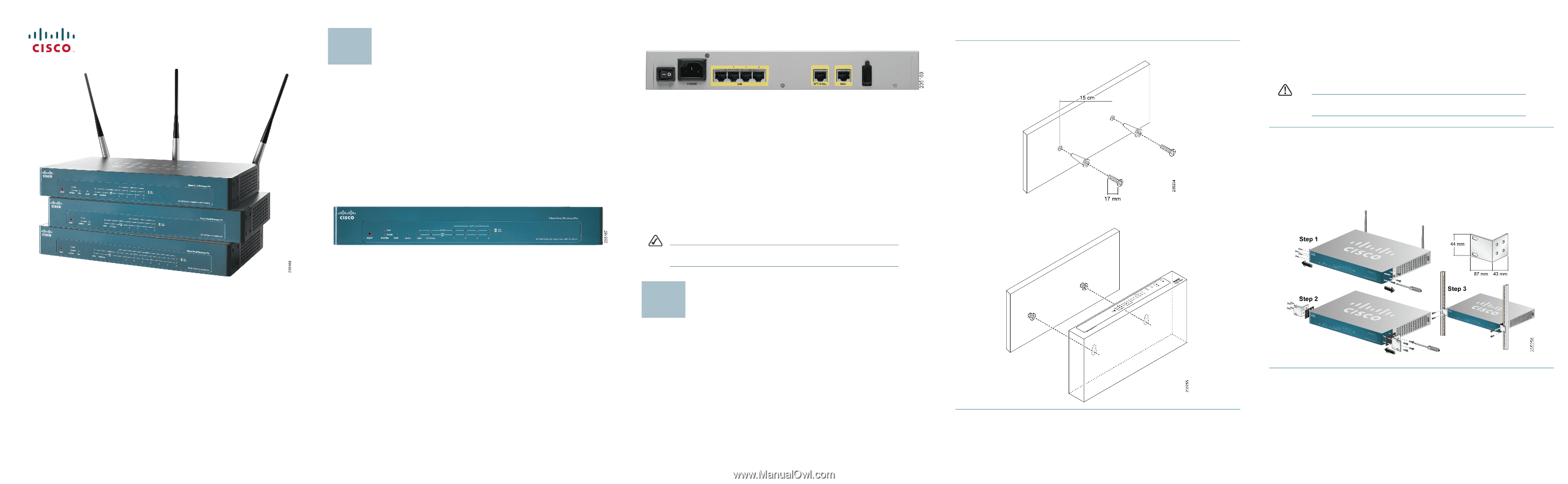
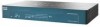
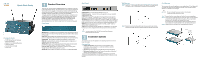
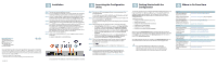
Quick Start Guide Cisco Small Business Pro SA 500 Series Security Appliances Package Contents • SA500 Series Security Appliance • Mounting Hardware • Rubber Feet for Desktop Mounting • Quick Start Guide • Documentation CD-ROM • Power Cord 1 Product Overview Thank you for choosing a Cisco SA500 Series Security Appliance, a member of the Small Business Family. The SA500 Series is a set of security appliances that provide business-grade security gateway solutions with firewall, site-tosite and remote access VPN support, and optional web and email security. The SA520W model also includes 802.11n access point capabilities. This guide describes the features of the security appliance, and helps you to install the device in a standard configuration. Your particular model may not have all of the features or functionality described in this guide. For more detailed information on the individual models, refer to the SA500 Series Security Appliances Administration Guide on Cisco.com. See the documentation links in the "Where to Go From Here" section of this guide. Front Panel RESET Button-To reboot the security appliance, push and release the Reset button. To restore the factory default settings, press and hold the Reset button for 5 seconds. DIAG LED-(Orange) When lit, indicates the appliance is performing the power-on diagnostics. When off, indicates the appliance has booted properly. POWER LED-(Green) When lit, indicates the appliance is powered on. DMZ LED-(Green) When lit, indicates the Optional port is configured as a separate LAN to host public servers. SPEED LED-(Green or Orange) Indicates the traffic rate for the associated port. Off = 10 Mbps, Green = 100 Mbps, Orange = 1000 Mbps. LINK/ACT LED-(Green) When lit, indicates a connection is being made through the port. When flashing, the port is active. WLAN LED-(Green) When lit, indicates that wireless is enabled (SA520W). Back Panel POWER Switch-Turns the security appliance on or off. POWER Connector-Connects the security appliance to power using the supplied power cable. LAN Ports-Connect PCs and other network appliances to the security appliance. The SA520 and SA520W have 4 LAN ports. The SA 540 has 8. OPTIONAL Port-Can be configured to operate as a WAN, LAN, or DMZ port. A DMZ (Demilitarized Zone or Demarcation Zone) can be configured to allow public access to services such as web servers without exposing your LAN. WAN Port-Connects the security appliance to DSL, a cable modem, or another WAN connectivity device. USB Port-Connects the security appliance to a USB device. You can use a USB device to store configuration files for backup and restore operations. NOTE The back panel of the SA520W includes three threaded connectors for the antennas. 2 Installation Options You can place your security appliance on a desktop, mount it on a wall, or mount it in a rack. Placement Tips • Ambient Temperature-To prevent the security appliance from overheating, do not operate it in an area that exceeds an ambient temperature of 104°F (40°C). • Air Flow-Be sure that there is adequate air flow around the device. • Mechanical Loading-Be sure that the security appliance is level and stable to avoid any hazardous conditions. To place the security appliance on a desktop, install the four rubber feet (included) on the bottom of the security appliance. Place the device on a flat surface. Wall Mounting STEP 1 Insert two 17 mm screws, with anchors, into the wall 15 cm apart (about 5.9 inches). Leave 3-4 mm (about 1/8 inch) of the head exposed. STEP 2 Position the unit so that the wall-mount slots are over the two screws. Slide the unit down until the screws fit snugly into the wall-mount slots. Rack Mounting You can mount the security appliance in any standard size, 19-inch (about 48 cm) wide rack. Each security appliance requires 1 rack unit (RU) of space, which is 1.75 inches (44.45 mm) high. CAUTION Do not overload the power outlet or circuit when installing multiple devices in a rack. STEP 1 Remove the four screws from each side of the security appliance. STEP 2 Place one of the supplied spacers on the side of the security appliance so that the four holes align to the screw holes. Place a rack mount bracket next to the spacer and reinstall the screws. If the screws are not long enough to reattach the bracket with the spacer, attach the bracket directly to the case without the spacer. STEP 3 Install the security appliance into a standard rack as shown.
-
 1
1 -
 2
2
 |
 |