Cisco SF100D-08 Quick Start Guide - Page 5
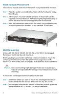
Connecting Network Devices - 8 port switch
 |
View all Cisco SF100D-08 manuals
Add to My Manuals
Save this manual to your list of manuals |
Page 5 highlights
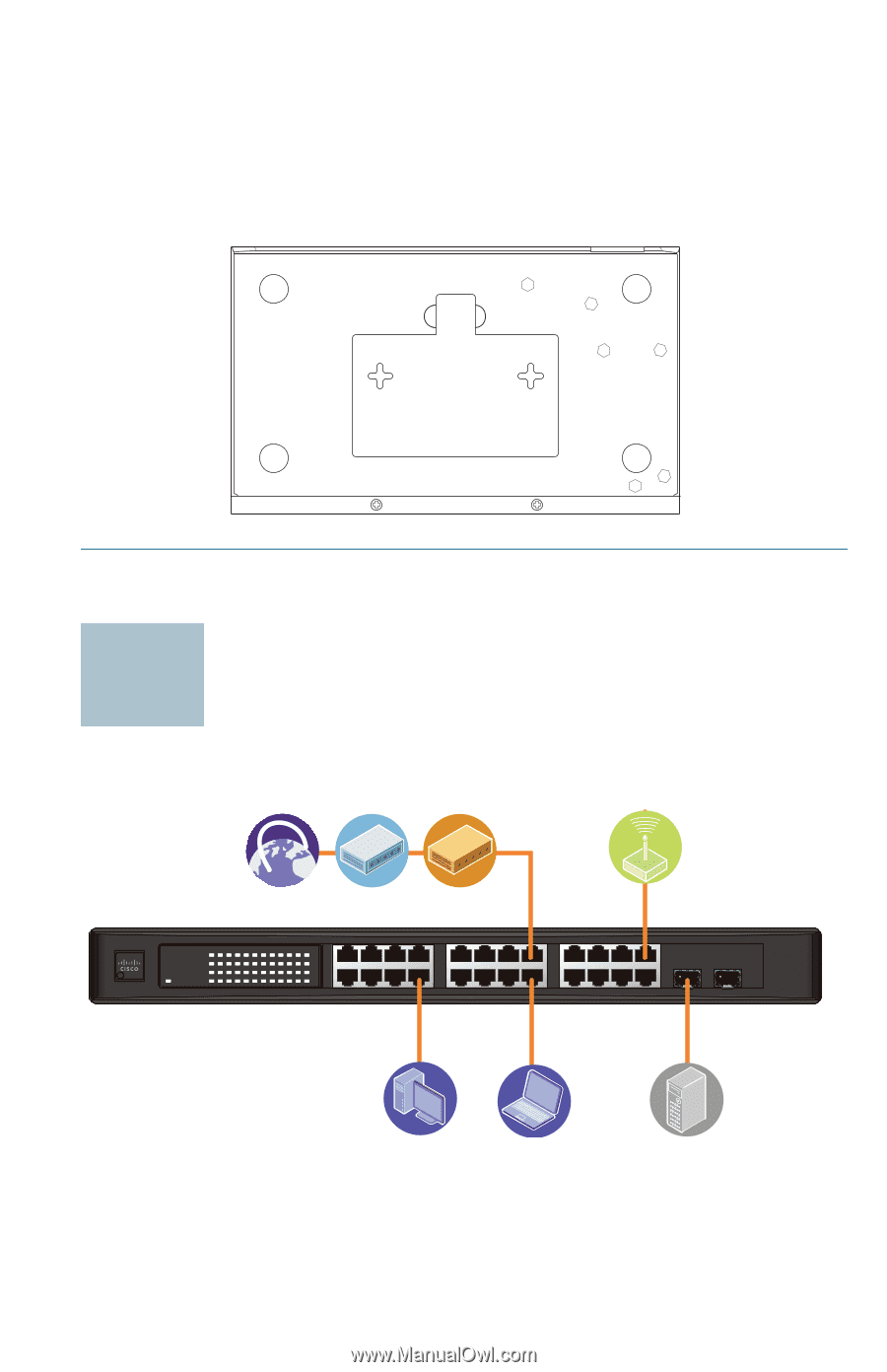
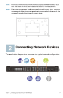
STEP 3 Insert a screw into each hole, leaving a gap between the surface and the base of the screw head of at least 0.1 inches (3 mm). STEP 4 Place the unmanaged rackmount switch wall-mount slots over the screws and slide the unmanaged rackmount switch down until the screws fit snugly into the wall-mount slots. 276583 2 Connecting Network Devices The application diagram is an example of a typical network configuration. SYSTEM Link/Act 1 2 34 56 7 8 9 10 11 12 / miniGBIC1 Gigabit Link/Act 13 14 15 16 17 18 19 20 21 22 23 24 / miniGBIC2 Gigabit 1 2 3 4 13 14 15 16 5 6 7 8 17 18 19 20 9 10 11 12 21 22 23 24 (Shared with 12) (Shared with 24) miniGBIC1 miniGBIC2 Cisco Small Business SR2024 24-P or t 10/ 100/ 1000 Swit ch 193803 Cisco Unmanaged Rackmount Switches 4
-
 1
1 -
 2
2 -
 3
3 -
 4
4 -
 5
5 -
 6
6 -
 7
7 -
 8
8 -
 9
9 -
 10
10 -
 11
11 -
12
 |
 |