Cisco SFE2000 Administration Guide - Page 12
Uplink Ports, The Back Panel - console port
 |
UPC - 745883572106
View all Cisco SFE2000 manuals
Add to My Manuals
Save this manual to your list of manuals |
Page 12 highlights
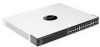
Chapter Linksys One Ready Communications Solution Uplink Ports 2 The Switch is equipped with 4 uplink ports and 2 mini-GBIC uplink ports. G1-G4 GBIC1/2 Ports G1-G4 are Ethernet (IEEE 802.3ab) uplink ports which support network speeds of 10Mbps, 100Mbps, and 1000Mbps. Ports G3 and G4 are shared with GBIC1 and GBIC2 ports, respectively. If shared ports pairs are both connected, then the mini-GBIC port takes priority. In stacking mode, two ports are used for stacking. Use only ports G1/ G2 for stacking. In standalone mode, all four ports can be used as uplinks. The Switch provides two mini-GBIC ports. The mini-GBIC port is a connection point for a mini-GBIC expansion module, so the Switch can be uplinked via fiber or copper to another switch. Each mini-GBIC port provides a link to a high-speed network segment or individual workstation at speeds of up to 1000Mbps. Use the Linksys MGBT1, MGBSX1, or MGBLH1 mini-GBIC modules with the Switch. The MGBSX1 and the MGBLH1 require fiber cabling with LC connectors, while the MGBT1 requires a Category 5e Ethernet cable with an RJ-45 connector. The Back Panel The power port is located on the back panel of the Ethernet switch. Power Port. The Power port is where you will 1 connect the power cord. For more details, refer to "Power Port," on page 7. Console Port. The Console port is where you can 2 connect a serial cable to a PC's serial port for configuration. For more details, refer to "Console Port," on page 7. 3 RPS Port. Redundant Power Supply (RPS) port. For more details, refer to "RPS Port," on page 7. 1 2 3 DC INPUT FOR REMOTE POWER SUPPLY SPECIFIED IN MANUAL +12V, 7.5A 6 Chapter 2: Getting to Know the Switch The Back Panel
-
 1
1 -
2
-
3
-
4
-
5
-
6
-
 7
7 -
 8
8 -
 9
9 -
 10
10 -
 11
11 -
 12
12 -
 13
13 -
 14
14 -
 15
15 -
 16
16 -
 17
17 -
18
-
19
-
20
-
21
-
22
-
23
-
24
-
25
-
26
-
27
-
28
-
29
-
30
-
31
-
32
-
33
-
34
-
35
-
36
-
37
-
38
-
39
-
40
-
41
-
42
-
43
-
44
-
45
-
46
-
47
-
48
-
49
-
50
-
51
-
52
-
53
-
54
-
55
-
56
-
57
-
58
-
59
-
60
-
61
-
62
-
63
-
64
-
65
-
66
-
67
-
68
-
69
-
70
-
71
-
72
 |
 |
