Cisco SRW2024-K9-NA User Manual - Page 3
Rack-Mount Placement, Wall Mounting, Mechanical Overloading, Circuit Overloading - switch
 |
View all Cisco SRW2024-K9-NA manuals
Add to My Manuals
Save this manual to your list of manuals |
Page 3 highlights
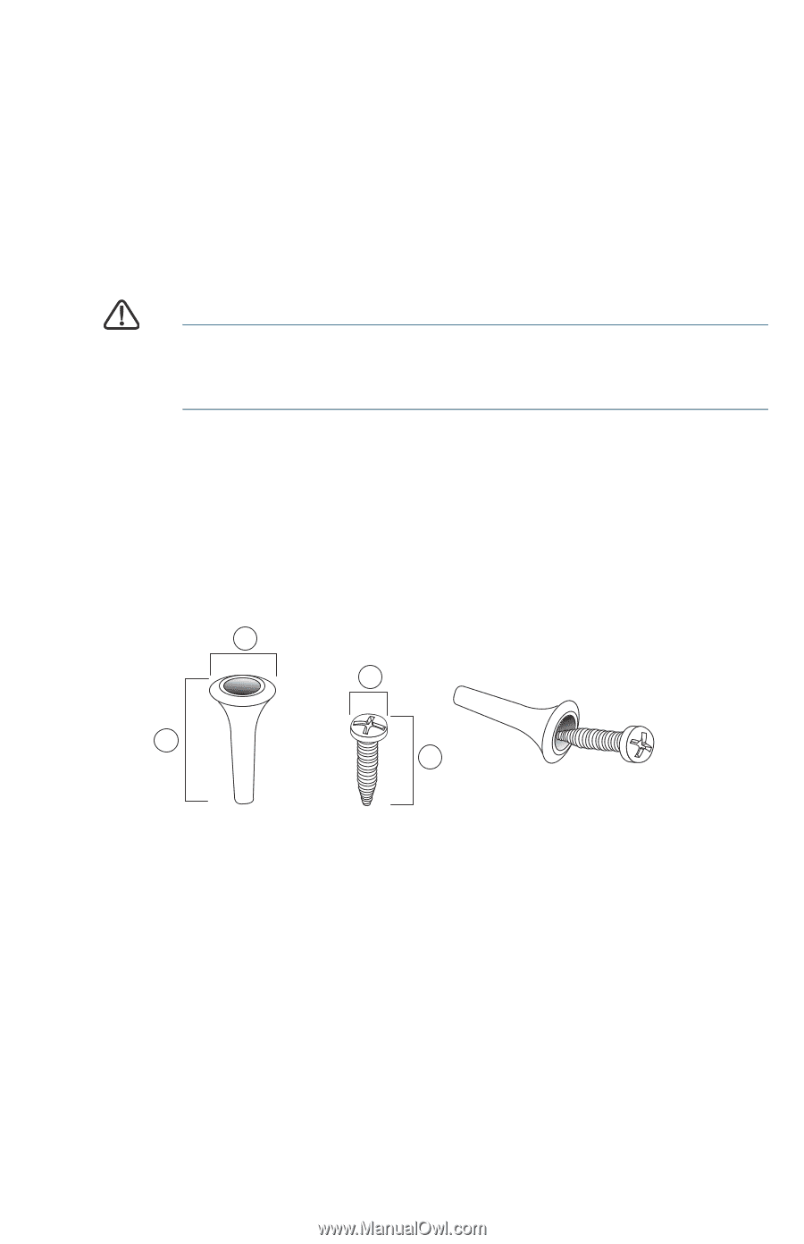
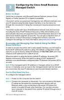
Mechanical Overloading-The device should be level, stable, and secure to prevent it from sliding or shifting out of position. Circuit Overloading-Adding the device to the power outlet must not overload that circuit. Rack-Mount Placement To rack-mount the switch in any standard rack, attach the rack-mount brackets to the sides of the switch with the supplied hardware and secure the brackets tightly. CAUTION For stability, load the rack from the bottom to the top, with the heaviest devices on the bottom. A top-heavy rack is likely to be unstable and may tip over. Wall Mounting Only the 8-port models of the switch can be wall-mounted. NOTE The switch should be mounted so that the ports face up or down. Do not mount the switch with the ports to the side. There is a wall-mount kit packed with your switch. The dimensions for the mount kit are as follows: 1 3 2 4 196243 1 8 mm/0.4 in 2 22.2 mm/0.9 in 3 6.8 mm/0.3 in 4 17.6 mm/0.7 in Mount the managed switch to the wall by drilling two pilot holes 3.7 inches (95 mm) apart, attaching the provided anchors and screws to the wall, then sliding the switch into position on the screws. The switch should have a minimum of 5 inches (130 mm) of clearance on all sides. 300 Series Managed Switches 3
-
 1
1 -
 2
2 -
 3
3 -
 4
4 -
 5
5 -
 6
6 -
 7
7 -
 8
8 -
 9
9 -
10
-
11
-
12
-
13
-
14
-
15
-
16
 |
 |