Cisco VWIC-2MFT-T1 Installation Instructions - Page 2
Physical Characteristics of the VWIC-2MFT-T1-DIR, VWIC-2MFT-E1-DIR - configuration
 |
UPC - 746320228402
View all Cisco VWIC-2MFT-T1 manuals
Add to My Manuals
Save this manual to your list of manuals |
Page 2 highlights
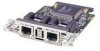
Each card also features protection switch solid state relays on the line interfaces, which together with redundancy logic and relay control added in a Cisco IOS feature set on the MWR 1941-DC router, can be used to provide T1/E1 Protection Switching between redundant routers in applicable implementations. Note For information on the Cisco MWR 1941-DC router implementations and Cisco IOS software available for those implementations, see the Cisco MWR 1941-DC Mobile Wireless Edge Router Software Configuration Guide. The Cisco MWR 1941-DC router provides three WAN interface slots, which allows support for 6 T1/E1s. Physical Characteristics of the VWIC-2MFT-T1-DIR, VWIC-2MFT-E1-DIR Each T1/E1 Multiflex VWIC provides two RJ-48C interfaces. You can distinguish between T1 and E1 Drop and Insert interface cards by the labeling on the faceplate, as shown in Figure 1 and Figure 2. Figure 1 2-Port T1 Multiflex Trunk Interface Card with Drop and Insert and Relays (VWIC-2MFT-T1-DIR) Front Panel RJ-48C ports 65781 AL SEE LP MANUAL VWIC CD BEFORE 2MFT-T1DIR CTRLR T1 1 INSTALLATION CTRLR T1 0 Figure 2 2-Port E1 Multiflex Trunk Interface Card with Drop and Insert and Relays (VWIC-2MFT-E1-DIR) Front Panel RJ-48C ports 65782 AL SEE LP MANUAL VWIC CD BEFORE 2MFT-E1DIR INSTALLATION CTRLR E1 1 CTRLR E1 0 Note The labeling under the port and on the lower left of the card indicates whether it is a T1 or E1 card. Also, due to limited space, the last dash was omitted from the label on the card (VWIC-2MFT-E1DIR and VWIC-2MFT-T1DIR). For information about the LEDs on the T1/E1 Multiflex VWIC, see Understanding the LEDs, page 12. For information about the pinout configuration for the RJ-48C connectors, see RJ-48C Pinout Configuration, page 11. VWIC-2MFT-T1-DIR, VWIC-2MFT-E1-DIR Installation Instructions 2 78-15842-01
-
 1
1 -
 2
2 -
 3
3 -
 4
4 -
 5
5 -
 6
6 -
 7
7 -
 8
8 -
9
-
10
-
11
-
12
-
13
-
14
-
15
-
16
-
17
-
18
 |
 |
