Cisco WS-C3560E48PDSF-RF Installation Guide - Page 29
Front-Panel Description
 |
UPC - 882658132667
View all Cisco WS-C3560E48PDSF-RF manuals
Add to My Manuals
Save this manual to your list of manuals |
Page 29 highlights
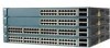
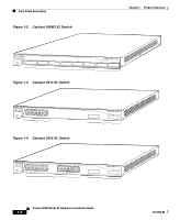
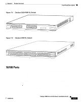
Chapter 1 Product Overview Front-Panel Description Table 1-2 Catalyst 3512, 3524, 3524-PWR, and 3548 XL Features (continued) Feature Description (continued) Management • Cisco IOS CLI through the console port or Telnet • CiscoView device-management application • Cluster Management Suite, a web-based tool for managing switch clusters or an individual switch through a single IP address • SNMP Power Redundancy • Connection for optional Cisco RPS 600 that operates on AC input and supplies DC output to the Catalyst 3512, 3524, and 3548 XL switches • Connection for optional Cisco RPS 300 that operates on AC input and supplies DC output to the Catalyst 3524-PWR XL switch Inline Power (Catalyst 3524-PWR XL switch only) • Ability to provide inline power for Cisco IP Phones from all 24 10/100 Ethernet ports • Auto-detection and control of inline phone power on a per-port basis on all 10/100 ports • Support for fan-fault and over-temperature detection through Visual Switch Manager (VSM) Front-Panel Description The front panel of the Catalyst 3508G XL switch (Figure 1-2) has eight 1000BaseX GBIC module slots but no 10/100 ports. The front panel of the Catalyst 3512, 3524, 3524-PWR and 3548 XL switches (Figure 1-3, Figure 1-4, Figure 1-5, and Figure 1-6) have 10/100 RJ-45 ports and two 1000BaseX GBIC module slots. All Catalyst 3500 XL switches have a set of LEDs and a Mode button. (The Catalyst 3548 XL switch has a Mode label that you press.) These front-panel components are described in this section. 78-6456-04 Catalyst 3500 Series XL Hardware Installation Guide 1-5
-
 1
1 -
2
-
3
-
4
-
5
-
6
-
7
-
8
-
9
-
10
-
11
-
12
-
13
-
14
-
15
-
16
-
17
-
18
-
19
-
20
-
21
-
22
-
23
-
 24
24 -
 25
25 -
 26
26 -
 27
27 -
 28
28 -
 29
29 -
 30
30 -
 31
31 -
 32
32 -
 33
33 -
 34
34 -
35
-
36
-
37
-
38
-
39
-
40
-
41
-
42
-
43
-
44
-
45
-
46
-
47
-
48
-
49
-
50
-
51
-
52
-
53
-
54
-
55
-
56
-
57
-
58
-
59
-
60
-
61
-
62
-
63
-
64
-
65
-
66
-
67
-
68
-
69
-
70
-
71
-
72
-
73
-
74
-
75
-
76
-
77
-
78
-
79
-
80
-
81
-
82
-
83
-
84
-
85
-
86
-
87
-
88
-
89
-
90
-
91
-
92
-
93
-
94
-
95
-
96
-
97
-
98
-
99
-
100
-
101
-
102
-
103
-
104
-
105
-
106
-
107
-
108
-
109
-
110
-
111
-
112
-
113
-
114
-
115
-
116
-
117
-
118
-
119
-
120
-
121
-
122
-
123
-
124
-
125
-
126
-
127
-
128
-
129
-
130
-
131
-
132
-
133
-
134
-
135
-
136
-
137
-
138
-
139
-
140
-
141
-
142
-
143
-
144
-
145
-
146
-
147
-
148
-
149
-
150
-
151
-
152
-
153
-
154
-
155
-
156
-
157
-
158
-
159
-
160
 |
 |