Cisco WS-X401310GE-RF Hardware Maintenance Manual - Page 50
Optical Bypass Switch Connections, Network Connection Considerations,
 |
UPC - 882658031861
View all Cisco WS-X401310GE-RF manuals
Add to My Manuals
Save this manual to your list of manuals |
Page 50 highlights
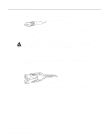
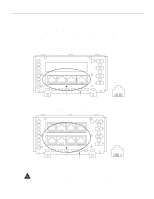
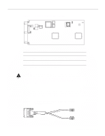
Network Connection Considerations Figure 2-29 Single-Attachment Multimode FDDI Module-End View LED PHY-S Multimode port Alignment groove PHY-S FDDI OPT-BYPASS PHY-S RING OPT Optical bypass switch connector H1401a Mounting screw locations Alignment groove Optical Bypass Switch Connections Both the dual-attachment and single-attachment FDDI modules have an optical bypass switch connector. An optical bypass switch is a passive optical device powered by the FDDI module. If a fault in the router occurs, or if power is lost, the optical bypass switch is enabled, and the ring will be unaffected. The optical bypass switch is automatically enabled if power is lost. In addition, the system software can enable the optical bypass switch if a problem is detected or if the operator chooses to take the router out of the ring. 2-28 Cisco 4000 Series Hardware Installation and Maintenance
-
 1
1 -
2
-
3
-
4
-
5
-
6
-
7
-
8
-
9
-
10
-
11
-
12
-
13
-
14
-
15
-
16
-
17
-
18
-
19
-
20
-
21
-
22
-
23
-
24
-
25
-
26
-
27
-
28
-
29
-
30
-
31
-
32
-
33
-
34
-
35
-
36
-
37
-
38
-
39
-
40
-
41
-
42
-
43
-
44
-
 45
45 -
 46
46 -
 47
47 -
 48
48 -
 49
49 -
 50
50 -
 51
51 -
 52
52 -
 53
53 -
 54
54 -
 55
55 -
56
-
57
-
58
-
59
-
60
-
61
-
62
-
63
-
64
-
65
-
66
-
67
-
68
-
69
-
70
-
71
-
72
-
73
-
74
-
75
-
76
-
77
-
78
-
79
-
80
-
81
-
82
-
83
-
84
-
85
-
86
-
87
-
88
-
89
-
90
-
91
-
92
-
93
-
94
-
95
-
96
-
97
-
98
-
99
-
100
-
101
-
102
-
103
-
104
-
105
-
106
-
107
-
108
-
109
-
110
-
111
-
112
-
113
-
114
-
115
-
116
-
117
-
118
-
119
-
120
-
121
-
122
-
123
-
124
-
125
-
126
-
127
-
128
-
129
-
130
-
131
-
132
-
133
-
134
-
135
-
136
-
137
-
138
-
139
-
140
-
141
-
142
-
143
 |
 |