Cisco WS-X401310GE-RF Hardware Maintenance Manual - Page 70
Single-Attachment FDDI Connections, Optical Bypass Switch later in
 |
UPC - 882658031861
View all Cisco WS-X401310GE-RF manuals
Add to My Manuals
Save this manual to your list of manuals |
Page 70 highlights
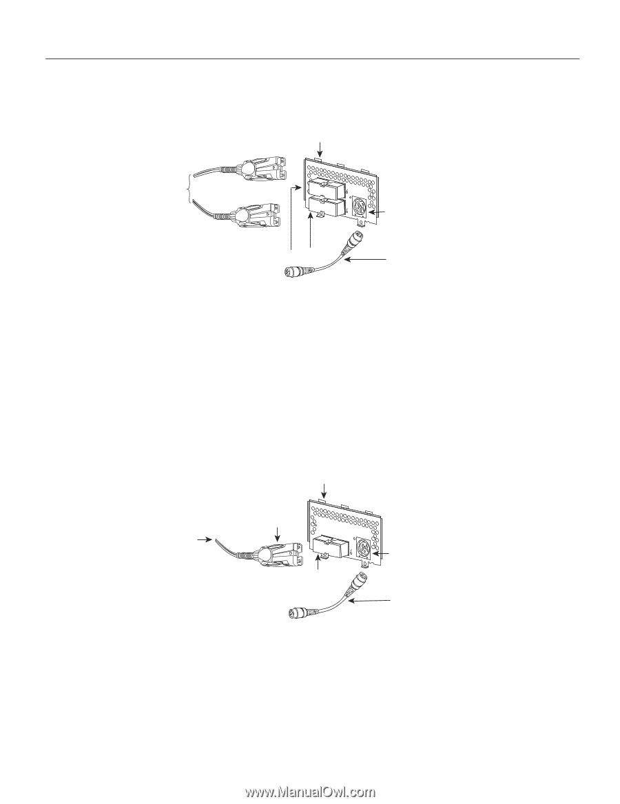
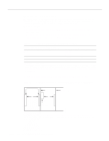
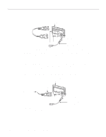
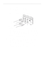
Making Network Connections Figure 3-10 Dual-Attachment FDDI Connections Dual attachment multimode FDDI module To optical bypass switch PHY-A (to PHY-B) PHY-B PHY-A RING OP FDDI OPT-BYPASS RING OP PHY-B (to PHY-A) PHY-B PHY-A Optical bypass switch connector (DIN) Optical bypass interface cable H1573a Step 2 Connect PHY-B on the FDDI module (the top port) to PHY-A on the other DAS. Step 3 When all your network connections are complete, proceed to the section "Connecting to an Optical Bypass Switch" later in this chapter. Single-Attachment FDDI Connections Step 1 Using a multimode fiber-optic cable, connect the single-attachment module's PHY-S port through a concentrator to a single-attachment ring, or connect it point-to-point directly to another device. (See Figure 3-11.) Figure 3-11 Making Single-Attachment Multimode FDDI Connections Single attachment multimode FDDI module RING OP H1575a To concentrator MIC connector PHY-S FDDI OPT-BYPASS PHY-S port Optical bypass switch connector (DIN) Optical bypass interface cable Step 2 When all your network connections are complete, proceed to the section "Connecting to an Optical Bypass Switch" later in this chapter. 3-12 Cisco 4000 Series Hardware Installation and Maintenance
-
 1
1 -
2
-
3
-
4
-
5
-
6
-
7
-
8
-
9
-
10
-
11
-
12
-
13
-
14
-
15
-
16
-
17
-
18
-
19
-
20
-
21
-
22
-
23
-
24
-
25
-
26
-
27
-
28
-
29
-
30
-
31
-
32
-
33
-
34
-
35
-
36
-
37
-
38
-
39
-
40
-
41
-
42
-
43
-
44
-
45
-
46
-
47
-
48
-
49
-
50
-
51
-
52
-
53
-
54
-
55
-
56
-
57
-
58
-
59
-
60
-
61
-
62
-
63
-
64
-
 65
65 -
 66
66 -
 67
67 -
 68
68 -
 69
69 -
 70
70 -
 71
71 -
 72
72 -
 73
73 -
 74
74 -
 75
75 -
76
-
77
-
78
-
79
-
80
-
81
-
82
-
83
-
84
-
85
-
86
-
87
-
88
-
89
-
90
-
91
-
92
-
93
-
94
-
95
-
96
-
97
-
98
-
99
-
100
-
101
-
102
-
103
-
104
-
105
-
106
-
107
-
108
-
109
-
110
-
111
-
112
-
113
-
114
-
115
-
116
-
117
-
118
-
119
-
120
-
121
-
122
-
123
-
124
-
125
-
126
-
127
-
128
-
129
-
130
-
131
-
132
-
133
-
134
-
135
-
136
-
137
-
138
-
139
-
140
-
141
-
142
-
143
 |
 |