Cobra 25 LX Operation Manual - Page 3
itive is the larger of the two - cb
 |
View all Cobra 25 LX manuals
Add to My Manuals
Save this manual to your list of manuals |
Page 3 highlights
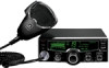
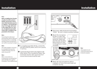
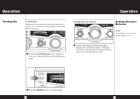
Installation Installation Note Before installing the CB radio, visually check the vehicle's battery connection to determine which terminal, positive or negative, is grounded (positive is the larger of the two) to the engine block (or chassis). A negatively grounded vehicle has its negative lead grounded to the chassis. Note Connecting the radio to an accessory fuse prevents the unit from being left on accidentally, and also permits operating the unit without running the engine. Note 4 In a negative grounded vehicle, connect the The radio should be connected to a constant 12V source to red lead of the DC power cord to an accessory 12 volt fuse. maintain the time when the radio is turned off. 5 Connect the black lead to the negative side of the vehicle. This is usually the chassis. Any Note When connected to an convenient location with a good electrical contact (remove paint) may be used. accessory fuse, unit will self test automatically when ignition is turned on. Turns itself on & off. 4 6 Plug power cable into back of unit marked "Power". Be sure to observe polarity markings. 7 Mount the microphone bracket on either side of the unit (driver's left) using two screws sup- plied. Bracket should be placed under the dash so microphone is readily accesCHs9i/b19le. 1 2 3 4 TX PWR TX CB / PA RX NB SIG 1 3 5 7 9 +30dB VOL SQ MENU PU SH ENTER SCAN / M SCAN MEM NB Note DIM / ESC If microphone is not RF GAINconneDcYtNeAdM,IKaEudio will not be heard at speaker. OFF MIN MAX MIN 8 Attach the 4-pin microphone cable to receptacle on front of unit and install unit in bracket securely. 5
-
 1
1 -
 2
2 -
 3
3 -
 4
4 -
 5
5 -
 6
6 -
 7
7 -
 8
8 -
 9
9 -
10
-
11
-
12
-
13
-
14
-
15
-
16
-
17
-
18
-
19
-
20
-
21
-
22
 |
 |
