Compaq 6000 Hardware Reference Guide - HP Compaq 6000 Pro Microtower Model - Page 27
Drive Positions, Computer Setup F10 Utility Guide
 |
UPC - 894582579463
View all Compaq 6000 manuals
Add to My Manuals
Save this manual to your list of manuals |
Page 27 highlights
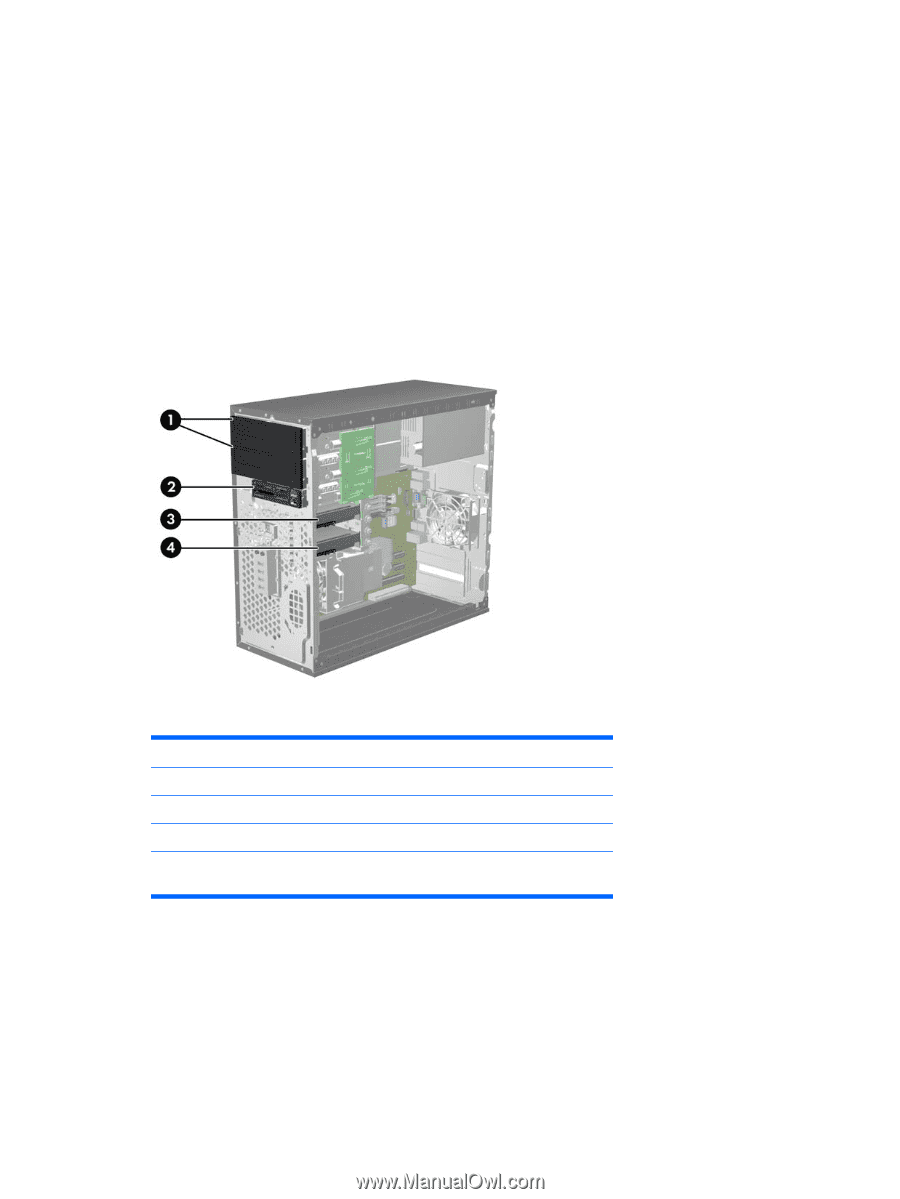
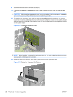
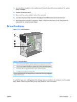
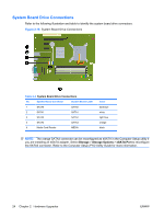
13. Connect external cables to the installed card, if needed. Connect internal cables to the system board, if needed. 14. Replace the access panel. 15. Reconnect the power cord and turn on the computer. 16. Lock any security devices that were disengaged when the access panel was removed. 17. Reconfigure the computer, if necessary. Refer to the Computer Setup (F10) Utility Guide for instructions on using Computer Setup. Drive Positions Figure 2-16 Drive Positions Table 2-3 Drive Positions 1 Two 5.25-inch external drive bays for optional drives (optical drives shown) 2 One 3.5-inch external drive bay for optional drive (media card reader shown) 3 Secondary 3.5-inch internal hard drive bay for optional hard drive 4 Primary 3.5-inch internal hard drive bay The drive configuration on your computer may be different than the drive configuration in the illustration above. To verify the type, size, and capacity of the storage devices installed in the computer, run Computer Setup. Refer to the Computer Setup (F10) Utility Guide for more information. ENWW Drive Positions 21
-
 1
1 -
2
-
3
-
4
-
5
-
6
-
7
-
8
-
9
-
10
-
11
-
12
-
13
-
14
-
15
-
16
-
17
-
18
-
19
-
20
-
21
-
 22
22 -
 23
23 -
 24
24 -
 25
25 -
 26
26 -
 27
27 -
 28
28 -
 29
29 -
 30
30 -
 31
31 -
 32
32 -
33
-
34
-
35
-
36
-
37
-
38
-
39
-
40
-
41
-
42
-
43
-
44
-
45
-
46
-
47
-
48
-
49
-
50
-
51
-
52
-
53
-
54
-
55
-
56
-
57
-
58
-
59
-
60
-
61
 |
 |