Compaq C300 HP G3000 Notebook PC and Compaq Presario C300 Notebook PC - Mainte - Page 110
from the socket at an angle, Remove the Mini Card module by pulling the module away
 |
UPC - 844986083011
View all Compaq C300 manuals
Add to My Manuals
Save this manual to your list of manuals |
Page 110 highlights
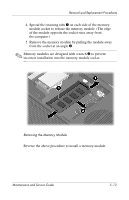
Removal and Replacement Procedures 3. Make note of which antenna cable is attached to which antenna clip on the Mini Card module, and then disconnect the auxiliary and main antenna cables 1 from the Mini Card module. 4. Remove the two Phillips PM2.0×4.0 screws 2 that secure the Mini Card module to the computer. 5. Remove the Mini Card module by pulling the module away from the socket at an angle 3. ✎ Mini Card modules are designed with a notch 4 to prevent incorrect installation into the Mini Card module socket. Removing a Mini Card Module Reverse the above procedure to install a Mini Card module. 5-16 Maintenance and Service Guide
-
 1
1 -
2
-
3
-
4
-
5
-
6
-
7
-
8
-
9
-
10
-
11
-
12
-
13
-
14
-
15
-
16
-
17
-
18
-
19
-
20
-
21
-
22
-
23
-
24
-
25
-
26
-
27
-
28
-
29
-
30
-
31
-
32
-
33
-
34
-
35
-
36
-
37
-
38
-
39
-
40
-
41
-
42
-
43
-
44
-
45
-
46
-
47
-
48
-
49
-
50
-
51
-
52
-
53
-
54
-
55
-
56
-
57
-
58
-
59
-
60
-
61
-
62
-
63
-
64
-
65
-
66
-
67
-
68
-
69
-
70
-
71
-
72
-
73
-
74
-
75
-
76
-
77
-
78
-
79
-
80
-
81
-
82
-
83
-
84
-
85
-
86
-
87
-
88
-
89
-
90
-
91
-
92
-
93
-
94
-
95
-
96
-
97
-
98
-
99
-
100
-
101
-
102
-
103
-
104
-
 105
105 -
 106
106 -
 107
107 -
 108
108 -
 109
109 -
 110
110 -
 111
111 -
 112
112 -
 113
113 -
 114
114 -
 115
115 -
116
-
117
-
118
-
119
-
120
-
121
-
122
-
123
-
124
-
125
-
126
-
127
-
128
-
129
-
130
-
131
-
132
-
133
-
134
-
135
-
136
-
137
-
138
-
139
-
140
-
141
-
142
-
143
-
144
-
145
-
146
-
147
-
148
-
149
-
150
-
151
-
152
-
153
-
154
-
155
-
156
-
157
-
158
-
159
-
160
-
161
-
162
-
163
-
164
-
165
-
166
-
167
-
168
-
169
-
170
-
171
-
172
-
173
-
174
-
175
-
176
-
177
-
178
-
179
-
180
-
181
-
182
-
183
-
184
-
185
-
186
-
187
-
188
-
189
-
190
-
191
-
192
-
193
-
194
-
195
-
196
-
197
-
198
-
199
-
200
-
201
-
202
-
203
-
204
-
205
-
206
-
207
-
208
-
209
-
210
-
211
-
212
-
213
-
214
-
215
-
216
-
217
-
218
-
219
-
220
-
221
-
222
-
223
-
224
-
225
-
226
-
227
-
228
-
229
-
230
-
231
-
232
-
233
-
234
-
235
-
236
-
237
-
238
-
239
-
240
-
241
-
242
-
243
-
244
 |
 |

5–16
Maintenance and Service Guide
Removal and Replacement Procedures
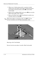
3. Make note of which antenna cable is attached to which
antenna clip on the Mini Card module, and then disconnect
the auxiliary and main antenna cables
1
from the Mini
Card module.
4.
Remove the two Phillips PM2.0×4.0 screws
2
that secure the
Mini Card module to the computer.
5. Remove the Mini Card module by pulling the module away
from the socket at an angle
3
.
✎
Mini Card modules are designed with a notch
4
to prevent
incorrect installation into the Mini Card module socket.
Removing a Mini Card Module
Reverse the above procedure to install a Mini Card module.