Compaq Mini CQ10-400 HP Mini 110 and Compaq Mini CQ10 - Maintenance and Servic - Page 76
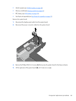
Remove the two Phillips PM2.0×4.0 screws, that secure the display assembly to the base
 |
View all Compaq Mini CQ10-400 manuals
Add to My Manuals
Save this manual to your list of manuals |
Page 76 highlights
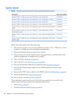
7. Release the wireless antenna cables (2) from the clip built into the base enclosure. CAUTION: Support the display assembly when removing the following screws. Failure to support the display assembly can result in damage to the display assembly and other device components. 8. Remove the two Phillips PM2.0×4.0 screws (1) that secure the display assembly to the base enclosure. 66 Chapter 4 Removal and replacement procedures
-
 1
1 -
2
-
3
-
4
-
5
-
6
-
7
-
8
-
9
-
10
-
11
-
12
-
13
-
14
-
15
-
16
-
17
-
18
-
19
-
20
-
21
-
22
-
23
-
24
-
25
-
26
-
27
-
28
-
29
-
30
-
31
-
32
-
33
-
34
-
35
-
36
-
37
-
38
-
39
-
40
-
41
-
42
-
43
-
44
-
45
-
46
-
47
-
48
-
49
-
50
-
51
-
52
-
53
-
54
-
55
-
56
-
57
-
58
-
59
-
60
-
61
-
62
-
63
-
64
-
65
-
66
-
67
-
68
-
69
-
70
-
 71
71 -
 72
72 -
 73
73 -
 74
74 -
 75
75 -
 76
76 -
 77
77 -
 78
78 -
 79
79 -
 80
80 -
 81
81 -
82
-
83
-
84
-
85
-
86
-
87
-
88
-
89
-
90
-
91
-
92
-
93
-
94
-
95
-
96
-
97
-
98
-
99
-
100
-
101
-
102
-
103
-
104
-
105
-
106
-
107
-
108
-
109
-
110
-
111
-
112
-
113
-
114
-
115
 |
 |

7.
Release the wireless antenna cables
(2)
from the clip built into the base enclosure.
CAUTION:
Support the display assembly when removing the following screws. Failure to
support the display assembly can result in damage to the display assembly and other device
components.
8.
Remove the two Phillips PM2.0×4.0 screws
(1)
that secure the display assembly to the base
enclosure.
66
Chapter 4
Removal and replacement procedures