Compaq Mini CQ10-400 HP Mini 110 and Compaq Mini CQ10 - Maintenance and Servic - Page 79
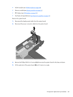
Remove the Phillips PM2.0×4.0 screw, that secures the system board to the base enclosure.
 |
View all Compaq Mini CQ10-400 manuals
Add to My Manuals
Save this manual to your list of manuals |
Page 79 highlights
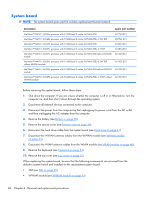
● WLAN module (see WLAN module on page 46) ● Memory module (see Memory module on page 51) ● RTC battery (see RTC battery on page 53) ● Fan/heat sink assembly (see Fan/heat sink assembly on page 71) Remove the system board: 1. Disconnect the display panel cable from the system board. 2. Disconnect the power connector cable from the system board. 3. Remove the Phillips PM2.0×4.0 screw (1) that secures the system board to the base enclosure. 4. Lift the right side of the system board (2) until it rests at an angle. Component replacement procedures 69
-
 1
1 -
2
-
3
-
4
-
5
-
6
-
7
-
8
-
9
-
10
-
11
-
12
-
13
-
14
-
15
-
16
-
17
-
18
-
19
-
20
-
21
-
22
-
23
-
24
-
25
-
26
-
27
-
28
-
29
-
30
-
31
-
32
-
33
-
34
-
35
-
36
-
37
-
38
-
39
-
40
-
41
-
42
-
43
-
44
-
45
-
46
-
47
-
48
-
49
-
50
-
51
-
52
-
53
-
54
-
55
-
56
-
57
-
58
-
59
-
60
-
61
-
62
-
63
-
64
-
65
-
66
-
67
-
68
-
69
-
70
-
71
-
72
-
73
-
 74
74 -
 75
75 -
 76
76 -
 77
77 -
 78
78 -
 79
79 -
 80
80 -
 81
81 -
 82
82 -
 83
83 -
 84
84 -
85
-
86
-
87
-
88
-
89
-
90
-
91
-
92
-
93
-
94
-
95
-
96
-
97
-
98
-
99
-
100
-
101
-
102
-
103
-
104
-
105
-
106
-
107
-
108
-
109
-
110
-
111
-
112
-
113
-
114
-
115
 |
 |

●
WLAN module (see
WLAN module
on page
46
)
●
Memory module (see
Memory module
on page
51
)
●
RTC battery (see
RTC battery
on page
53
)
●
Fan/heat sink assembly (see
Fan/heat sink assembly
on page
71
)
Remove the system board:
1.
Disconnect the display panel cable from the system board.
2.
Disconnect the power connector cable from the system board.
3.
Remove the Phillips PM2.0×4.0 screw
(1)
that secures the system board to the base enclosure.
4.
Lift the right side of the system board
(2)
until it rests at an angle.
Component replacement procedures
69