Compaq Presario CQ36-100 Compaq Presario CQ35 and CQ36 Notebook PC - Maintenan - Page 91
System board, Keyboard cover see
 |
View all Compaq Presario CQ36-100 manuals
Add to My Manuals
Save this manual to your list of manuals |
Page 91 highlights
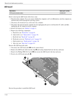
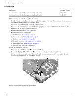
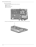
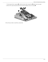
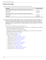
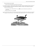
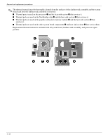
Removal and replacement procedures System board ✎ The system board spare part kit includes replacement thermal material. Description For use only with CQ35 computer models: For use only with CQ35-101-299 computer models with discrete memory graphics subsystems For use only with CQ35-101-299 computer models with UMA memory graphics subsystems For use only with CQ35-301-499 computer models with discrete memory graphics subsystems For use only with CQ35-301-499 computer models with UMA memory graphics subsystems For use only with CQ36 computer models: For use only with computer models with UMA memory graphics subsystems For use only with computer models with discrete memory graphics subsystems Spare part number 538765-002 538766-001 576797-001 576798-001 591415-001 591416-001 Before removing the system board, follow these steps: 1. Shut down the computer. If you are unsure whether the computer is off or in Hibernation, turn the computer on, and then shut it down through the operating system. 2. Disconnect all external devices connected to the computer. 3. Disconnect the power from the computer by first unplugging the power cord from the AC outlet, and then unplugging the AC adapter from the computer. 4. Remove the battery (see "Battery" on page 7). 5. Remove the following components: a. Hard drive (see "Hard drive" on page 8) b. Memory module (see "Memory module" on page 11) c. WLAN module (see "WLAN module" on page 12) d. Optical drive (see "Optical drive" on page 20) e. Keyboard (see "Keyboard" on page 22) f. Keyboard cover (see "Keyboard cover" on page 24) g. Right speaker (see "Right speaker" on page 26) h. Top cover (see "Top cover" on page 27). i. Left speaker (see "Left speaker" on page 31) j. Display assembly (see "Display assembly" on page 32). When replacing the system board, be sure that the following additional components are removed from the defective system board and installed on the replacement system board: ■ RTC battery (see "RTC battery" on page 19) ■ Heat sink (see "Fan/heat sink assembly" on page 46) ■ Processor (see "Processor" on page 51) 4-43
-
 1
1 -
2
-
3
-
4
-
5
-
6
-
7
-
8
-
9
-
10
-
11
-
12
-
13
-
14
-
15
-
16
-
17
-
18
-
19
-
20
-
21
-
22
-
23
-
24
-
25
-
26
-
27
-
28
-
29
-
30
-
31
-
32
-
33
-
34
-
35
-
36
-
37
-
38
-
39
-
40
-
41
-
42
-
43
-
44
-
45
-
46
-
47
-
48
-
49
-
50
-
51
-
52
-
53
-
54
-
55
-
56
-
57
-
58
-
59
-
60
-
61
-
62
-
63
-
64
-
65
-
66
-
67
-
68
-
69
-
70
-
71
-
72
-
73
-
74
-
75
-
76
-
77
-
78
-
79
-
80
-
81
-
82
-
83
-
84
-
85
-
 86
86 -
 87
87 -
 88
88 -
 89
89 -
 90
90 -
 91
91 -
 92
92 -
 93
93 -
 94
94 -
 95
95 -
 96
96 -
97
-
98
-
99
-
100
-
101
-
102
-
103
-
104
-
105
-
106
-
107
-
108
-
109
-
110
-
111
-
112
-
113
-
114
-
115
-
116
-
117
-
118
-
119
-
120
-
121
-
122
-
123
-
124
-
125
-
126
-
127
-
128
-
129
-
130
-
131
-
132
-
133
-
134
-
135
-
136
-
137
-
138
-
139
-
140
-
141
-
142
-
143
-
144
-
145
-
146
-
147
-
148
-
149
-
150
-
151
-
152
-
153
-
154
 |
 |