Compaq Presario CQ41-200 Compaq Presario CQ41 Notebook PC - Maintenance and S - Page 65
To replace the display bezel or any of the display assembly internal components
 |
View all Compaq Presario CQ41-200 manuals
Add to My Manuals
Save this manual to your list of manuals |
Page 65 highlights
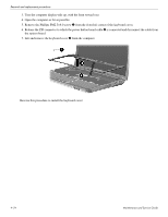
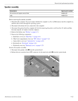
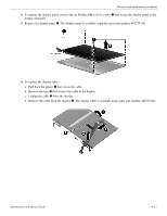
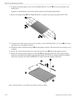
Removal and replacement procedures 7. Remove the four Phillips PM2.5×6.0 screws 1 that secure the display assembly to the computer. 8. Remove the display assembly 2. 9. To replace the display bezel or any of the display assembly internal components, remove the Mylar screw covers 1 and the two Phillips PM2.5×5.0 screws 2 on the display bezel lower edge.The display rubber screw covers are included in the Display Rubber Kit, spare part number 487283-001. Maintenance and Service Guide 4-29
-
 1
1 -
2
-
3
-
4
-
5
-
6
-
7
-
8
-
9
-
10
-
11
-
12
-
13
-
14
-
15
-
16
-
17
-
18
-
19
-
20
-
21
-
22
-
23
-
24
-
25
-
26
-
27
-
28
-
29
-
30
-
31
-
32
-
33
-
34
-
35
-
36
-
37
-
38
-
39
-
40
-
41
-
42
-
43
-
44
-
45
-
46
-
47
-
48
-
49
-
50
-
51
-
52
-
53
-
54
-
55
-
56
-
57
-
58
-
59
-
 60
60 -
 61
61 -
 62
62 -
 63
63 -
 64
64 -
 65
65 -
 66
66 -
 67
67 -
 68
68 -
 69
69 -
 70
70 -
71
-
72
-
73
-
74
-
75
-
76
-
77
-
78
-
79
-
80
-
81
-
82
-
83
-
84
-
85
-
86
-
87
-
88
-
89
-
90
-
91
-
92
-
93
-
94
-
95
-
96
-
97
-
98
-
99
-
100
-
101
-
102
-
103
-
104
-
105
-
106
-
107
-
108
-
109
-
110
-
111
-
112
-
113
-
114
-
115
-
116
-
117
-
118
-
119
-
120
-
121
-
122
-
123
-
124
-
125
-
126
-
127
-
128
-
129
-
130
-
131
-
132
-
133
-
134
 |
 |

Removal and replacement procedures
Maintenance and Service Guide
4–29
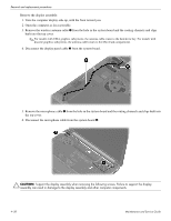
7. Remove the four Phillips PM2.5×6.0 screws
1
that secure the display assembly to the computer.
8. Remove the display assembly
2
.
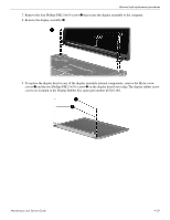
9. To replace the display bezel or any of the display assembly internal components, remove the Mylar screw
covers
1
and the two Phillips PM2.5×5.0 screws
2
on the display bezel lower edge.The display rubber screw
covers are included in the Display Rubber Kit, spare part number 487283-001.