Compaq Presario CQ41-200 Compaq Presario CQ41 Notebook PC - Maintenance and S - Page 72
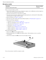
Two Phillips PM2.0×3.0 screws
 |
View all Compaq Presario CQ41-200 manuals
Add to My Manuals
Save this manual to your list of manuals |
Page 72 highlights
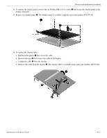
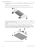
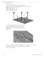
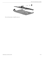
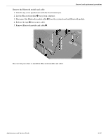
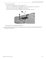
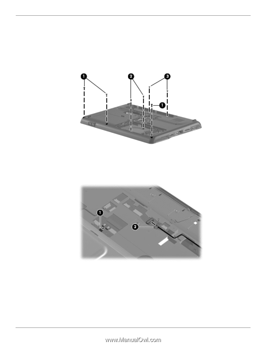
Removal and replacement procedures Remove the top cover: 1. Turn the computer upside down with the front toward you. 2. Remove the following screws that secure the top cover to the base enclosure: 1 Three Phillips PM2.5×10.0 screws 2 Two Phillips PM2.5×5.0 screws 3 Two Phillips PM2.0×3.0 screws 3. Turn the computer right-side up, with the front toward you. 4. Disconnect the following cables from the system board: 1 TouchPad cable with zero insertion force (ZIF) connector 2 USB cable 5. Remove the two Phillips PM2.5×6.0 screws 1 that secure the top cover to the base enclosure. 6. Lift up the front edge of the top cover until it releases from the base 2. 7. Remove the top cover 3. 4-36 Maintenance and Service Guide
-
 1
1 -
2
-
3
-
4
-
5
-
6
-
7
-
8
-
9
-
10
-
11
-
12
-
13
-
14
-
15
-
16
-
17
-
18
-
19
-
20
-
21
-
22
-
23
-
24
-
25
-
26
-
27
-
28
-
29
-
30
-
31
-
32
-
33
-
34
-
35
-
36
-
37
-
38
-
39
-
40
-
41
-
42
-
43
-
44
-
45
-
46
-
47
-
48
-
49
-
50
-
51
-
52
-
53
-
54
-
55
-
56
-
57
-
58
-
59
-
60
-
61
-
62
-
63
-
64
-
65
-
66
-
 67
67 -
 68
68 -
 69
69 -
 70
70 -
 71
71 -
 72
72 -
 73
73 -
 74
74 -
 75
75 -
 76
76 -
 77
77 -
78
-
79
-
80
-
81
-
82
-
83
-
84
-
85
-
86
-
87
-
88
-
89
-
90
-
91
-
92
-
93
-
94
-
95
-
96
-
97
-
98
-
99
-
100
-
101
-
102
-
103
-
104
-
105
-
106
-
107
-
108
-
109
-
110
-
111
-
112
-
113
-
114
-
115
-
116
-
117
-
118
-
119
-
120
-
121
-
122
-
123
-
124
-
125
-
126
-
127
-
128
-
129
-
130
-
131
-
132
-
133
-
134
 |
 |
4–36
Maintenance and Service Guide
Removal and replacement procedures
Remove the top cover:
1. Turn the computer upside down with the front toward you.
2. Remove the following screws that secure the top cover to the base enclosure:
1
Three Phillips PM2.5×10.0 screws
2
Two Phillips PM2.5×5.0 screws
3
Two Phillips PM2.0×3.0 screws
3. Turn the computer right-side up, with the front toward you.
4. Disconnect the following cables from the system board:
1
TouchPad cable with zero insertion force (ZIF) connector
2
USB cable
5. Remove the two Phillips PM2.5×6.0 screws
1
that secure the top cover to the base enclosure.
6. Lift up the front edge of the top cover until it releases from the base
2
.
7. Remove the top cover
3
.