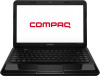
Compaq Presario CQ45-700 Maintenance and Service Guide
Compaq Presario CQ45-700 Manual
 |
View all Compaq Presario CQ45-700 manuals
Add to My Manuals
Save this manual to your list of manuals |
Compaq Presario CQ45-700 manual content summary:
- Compaq Presario CQ45-700 | Maintenance and Service Guide - Page 1
HP 1000 Notebook PC and Compaq Presario CQ45 Notebook PC Maintenance and Service Guide - Compaq Presario CQ45-700 | Maintenance and Service Guide - Page 2
of Intel Corporation in the U.S. and other countries. Microsoft and Windows are U.S. registered trademarks of Microsoft Corporation. SD Logo is a trademark for HP products and services are set forth in the express warranty statements accompanying such products and services. Nothing herein should be - Compaq Presario CQ45-700 | Maintenance and Service Guide - Page 3
Safety warning notice WARNING! To reduce the possibility of heat-related injuries or of overheating the device, do not place the device directly on your lap or obstruct the device air vents. Use the device only on a hard, flat surface. Do not allow another hard surface, such as an adjoining optional - Compaq Presario CQ45-700 | Maintenance and Service Guide - Page 4
iv Safety warning notice - Compaq Presario CQ45-700 | Maintenance and Service Guide - Page 5
Left side ...8 Display ...10 Top ...11 TouchPad ...11 Lights ...12 Buttons ...13 Keys ...14 Bottom ...15 3 Illustrated parts catalog ...16 Service tag ...16 Computer major components ...18 Display assembly subcomponents ...22 Mass storage devices ...24 Plastics Kit ...26 Miscellaneous parts ...27 - Compaq Presario CQ45-700 | Maintenance and Service Guide - Page 6
Service tag ...36 Computer feet ...37 Battery ...38 Display subcomponents (bezel, webcam, panel 39 WLAN module ...46 Memory module ...48 Hard drive ...50 RTC battery ...97 6 Specifications ...98 Computer specifications ...98 14.0-inch display specifications ...99 Hard drive specifications ...100 7 - Compaq Presario CQ45-700 | Maintenance and Service Guide - Page 7
a previous system restore point 105 Restoring specific files ...105 Restoring specific files using Windows Backup and Restore 105 Recovering the original system countries ...108 Requirements for specific countries and regions 109 9 Recycling ...111 Battery ...111 Display ...111 Index ...117 vii - Compaq Presario CQ45-700 | Maintenance and Service Guide - Page 8
viii - Compaq Presario CQ45-700 | Maintenance and Service Guide - Page 9
an Intel processor Product name Compaq Presario CQ45 Notebook PC √ HP 1000 Notebook PC √ √ Processors AMD E2-1800 1.70-GHz processor (1333-MHz memory √ speed, dual core, 18 W) NOTE: This processor is not available on computer models equipped with Windows 7 Starter 32 operating system. AMD - Compaq Presario CQ45-700 | Maintenance and Service Guide - Page 10
Graphics with 1024-MB of √ dedicated video memory (128Mx16 DDR3 900-MHz x 4 PCs; supports DirectX 11) NOTE: This graphics solution is not available on computer models equipped with Windows 7 Starter operating system. UMA graphics: AMD Radeon HD 7340 Graphics (on computer models √ equipped - Compaq Presario CQ45-700 | Maintenance and Service Guide - Page 11
in) hard drives in 9.5-mm (.37-in) and √ √ 7.0-mm (.28-in) thicknesses Customer-accessible √ √ Serial ATA √ √ Supports the following hard drives: √ √ ● 640-GB, 5400-rpm, 9.5-mm (not supported with Windows 7 Starter OS) ● 500-GB, 5400-rpm, 9.5-mm or 7.0-mm ● 320-GB, 5400-rpm, 9.5-mm or - Compaq Presario CQ45-700 | Maintenance and Service Guide - Page 12
output to wide-aspect vs. standard aspect video VGA (Dsub 15 pin) supporting 2048×1536 external resolution √ @ 75 Hz, hot plug and unplug and to wide-aspect vs. standard aspect video Keyboard/ pointing devices Full-size textured pocket keyboard √ √ TouchPad with multi-touch gestures, 2- - Compaq Presario CQ45-700 | Maintenance and Service Guide - Page 13
● 6-cell, 47-Whr, 2.20-Ah Li-ion battery Security cable slot √ √ Preinstalled: √ √ ● Windows 7 Professional (64-bit) ● Windows 7 Home Premium (64-bit) ● Windows 7 Home Basic (64-bit) ● Windows 7 Starter (32-bit, not supported on computer models equipped with a 640-GB hard drive) ● SUSE - Compaq Presario CQ45-700 | Maintenance and Service Guide - Page 14
2 External component identification Front Component Speakers (2) Description Produce sound. 6 Chapter 2 External component identification - Compaq Presario CQ45-700 | Maintenance and Service Guide - Page 15
drive is idle. Releases the disc tray. Connect optional USB devices. ● White: The AC adapter is connected and the battery is charged. ● Amber: The AC adapter is connected and the battery is charging. ● Off: The computer is using DC power. Connects an AC adapter. Attaches an optional security cable - Compaq Presario CQ45-700 | Maintenance and Service Guide - Page 16
, see the Regulatory, Safety and Environmental Notices. NOTE: When a device is connected to a headphone jack, the computer speakers are disabled. Supports the following digital card formats: ● Secure Digital (SD) Memory Card ● Secure Digital Extended Capacity (SDxC) Memory Card ● Secure Digital High - Compaq Presario CQ45-700 | Maintenance and Service Guide - Page 17
Component (9) (10) Hard drive light Power light Description ● Blinking white: The hard drive is being accessed. ● White: The computer is on. ● Blinking white: The computer is in the Sleep state, which is an energy-saving mode. The computer shuts off power to the display and other unneeded - Compaq Presario CQ45-700 | Maintenance and Service Guide - Page 18
notices, see the section of the Regulatory, Safety, and Environmental Notices that applies to your country or region. These notices are located in Help and Support. 10 Chapter 2 External component identification - Compaq Presario CQ45-700 | Maintenance and Service Guide - Page 19
button Description Turns the TouchPad on or off. ● On: The TouchPad is off. ● Off: The TouchPad is on. Moves the on-screen pointer and selects or activates items on the screen. Functions like the left button on an external mouse. Functions like the right button on an external mouse. Top 11 - Compaq Presario CQ45-700 | Maintenance and Service Guide - Page 20
Lights Component (1) Caps lock light (2) Power light (3) Wireless light Description On: Caps lock is on, which switches the keys to all capital letters. ● White: The computer is on. ● Blinking white: The computer is in the Sleep state, which is an energy-saving mode. The computer shuts off - Compaq Presario CQ45-700 | Maintenance and Service Guide - Page 21
the button down briefly to exit Hibernation. If the computer has stopped responding and Microsoft® Windows® shutdown procedures are ineffective, press and hold the power button down for at least 5 System and Security > Power Options, or refer to the user guides included with your computer. Top 13 - Compaq Presario CQ45-700 | Maintenance and Service Guide - Page 22
when pressed in combination with the fn key. Displays system information when pressed in combination with the esc key. Displays the Windows Start menu. Execute frequently used system functions. Displays a shortcut menu for items beneath the cursor. 14 Chapter 2 External component identification - Compaq Presario CQ45-700 | Maintenance and Service Guide - Page 23
internal fan to cycle on and off during routine operation. Releases the battery from the battery bay. Wireless and memory module compartment Hard drive bay Contains the wireless to restore computer functionality, and then contact support through Help and Support. Contains the hard drive. Bottom 15 - Compaq Presario CQ45-700 | Maintenance and Service Guide - Page 24
the product name affixed to the front of the computer. This is an alphanumeric identifier that is unique to each product. This number provides specific information about the product's hardware components. The part number helps a service technician to determine what components and parts are needed. - Compaq Presario CQ45-700 | Maintenance and Service Guide - Page 25
Item Description (4) Warranty period (5) Model description (select models only) Function This number describes the duration of the warranty period for the computer. This is the alphanumeric identifier used to locate documents, drivers, and support for the computer. Service tag 17 - Compaq Presario CQ45-700 | Maintenance and Service Guide - Page 26
Computer major components Item (1) (2) Component Spare part number Display assembly (not spared) NOTE: For display assembly spare part information, see Display assembly subcomponents on page 22. Keyboard (includes keyboard cable): 18 Chapter 3 Illustrated parts catalog - Compaq Presario CQ45-700 | Maintenance and Service Guide - Page 27
281 For use in the United States 646125-001 Power button board (includes cable) 685098-001 Top cover (includes TouchPad): For use with Compaq Presario CQ45 models: 685110-001 For use with HP 1000 models: 685109-001 Speakers (includes left and right speakers and cable) 685106-001 TouchPad - Compaq Presario CQ45-700 | Maintenance and Service Guide - Page 28
with an Intel Pentium or Celeron processor and a graphics subsystem with UMA video memory 685783-001 Power connector cable 685085-001 RTC battery 449137-001 Processor (includes replacement thermal materials): Intel Core i3-3110M 2.40-GHz processor (1600-MHz memory speed, 3.0-MB L3 cache, dual - Compaq Presario CQ45-700 | Maintenance and Service Guide - Page 29
Item (21) Component 6-cell, 55-Whr, 2.55-Ah Li-ion battery 6-cell, 47-Whr, 2.20-Ah Li-ion battery Optical drive (DVD±RW and CD-RW Super Multi Double-Layer Combo Drive; includes rear optical drive bracket but does not include optical drive cable - Compaq Presario CQ45-700 | Maintenance and Service Guide - Page 30
Display assembly subcomponents Item (1) (2) (3) Component Display bezel (includes Mylar screw covers): For use with Compaq Presario CQ45 models For use with HP 1000 models Webcam/microphone module: HP VGA webcam/microphone module 35.6-cm (14.0-in), HD, LED, BrightView display panel 22 - Compaq Presario CQ45-700 | Maintenance and Service Guide - Page 31
(includes wireless antenna cables and transceivers; also includes Mylar screw covers) Display enclosure (includes Mylar screw covers): For use with Compaq Presario CQ45 models: For use with HP 1000 models: Rubber display bumpers (not illustrated) Spare part number 685088-001 685090-001 685083-001 - Compaq Presario CQ45-700 | Maintenance and Service Guide - Page 32
Mass storage devices Item (1) Component Spare part number Hard drive (6.35-cm (2.5-in), SATA; does not include hard drive cable or bracket): NOTE: The hard drive cable and bracket are included in the Hard Drive Hardware Kit, spare part number 685089-001. 640-GB, 5400-rpm, 9.5-mm 669300-001 - Compaq Presario CQ45-700 | Maintenance and Service Guide - Page 33
Item (2a) (2b) (3) (4) Component Hard drive bracket Hard drive cable Optical drive (DVD±RW and CD-RW Super Multi Double-Layer Combo Drive; includes rear optical drive bracket but does not include optical drive cable or cable bracket) NOTE: The optical drive cable and cable bracket are included in - Compaq Presario CQ45-700 | Maintenance and Service Guide - Page 34
Plastics Kit Item (1) (2) Component Spare part number Plastics Kit, includes: 685100-001 Hard drive compartment cover (includes one captive screw, secured by a C-clip) Memory module/wireless module compartment cover (includes one captive screw, secured by a C-clip) 26 Chapter 3 Illustrated - Compaq Presario CQ45-700 | Maintenance and Service Guide - Page 35
Miscellaneous parts Component HP Smart AC adapter: For use with computer models equipped with discrete graphics: 90-W PFC RC V HP Smart AC adapter (for use in all countries except China and India) 90-W PFC RC V EM HP Smart AC adapter (for use in China and India only) For use with computer models - Compaq Presario CQ45-700 | Maintenance and Service Guide - Page 36
-001 641369-001 645193-001 646125-001 646125-161 646125-281 646125-AB1 646125-AD1 646125-D61 651046-001 652972-001 653338-001 Description RTC battery Power cord for use in North America (3-pin, black, 1.83-m) Power cord for use in Australia (3-pin, black, 1.83-m) Power cord for use in Europe - Compaq Presario CQ45-700 | Maintenance and Service Guide - Page 37
; also includes Mylar screw covers) Display enclosure for use with HP 1000 models (includes Mylar screw covers) Display enclosure for use with Compaq Presario CQ45 models (includes Mylar screw covers) Base enclosure (for use with all models) Display bezel for use with HP 1000 models (includes Mylar - Compaq Presario CQ45-700 | Maintenance and Service Guide - Page 38
video memory (includes replacement thermal materials) Top cover for use with HP 1000 models (includes TouchPad) Top cover for use with Compaq Presario CQ45 models (includes TouchPad) HP VGA webcam/microphone module System board for use only with computer models equipped with an Intel Pentium or - Compaq Presario CQ45-700 | Maintenance and Service Guide - Page 39
plastic parts. Use care when handling the plastic parts. Apply pressure only at the points designated in the maintenance instructions. Cables and connectors CAUTION: When servicing the computer, be sure that cables are placed in their proper locations during the reassembly process. Improper cable - Compaq Presario CQ45-700 | Maintenance and Service Guide - Page 40
Drive handling CAUTION: Drives are fragile components that must be handled with care. To prevent damage to the computer, damage to a drive, or loss of information, observe these precautions: Before removing or inserting a hard drive, shut down the computer. If you are unsure whether the computer is - Compaq Presario CQ45-700 | Maintenance and Service Guide - Page 41
CAUTION: A product can be degraded by as little as 700 V. Event Walking across carpet Walking across vinyl floor Motions of bench worker Removing DIPS from plastic tube Removing DIPS from vinyl tray Removing DIPS from Styrofoam Removing bubble pack from PCB Packing PCBs in foam-lined box Typical - Compaq Presario CQ45-700 | Maintenance and Service Guide - Page 42
. ● Use a wrist strap connected to a properly grounded work surface and use properly grounded tools and equipment. ● Use conductive field service tools, such as cutters, screwdrivers, and vacuums. ● When fixtures must directly contact dissipative surfaces, use fixtures made only of staticsafe - Compaq Presario CQ45-700 | Maintenance and Service Guide - Page 43
with ground cords of one megohm resistance ● Static-dissipative tables or floor mats with hard ties to the ground ● Field service kits ● Static awareness labels ● Material-handling packages ● Nonconductive plastic bags, tubes, or boxes ● Metal tote boxes ● Electrostatic voltage levels and - Compaq Presario CQ45-700 | Maintenance and Service Guide - Page 44
hardware components. The part number helps a service technician determine what components and parts are needed. This number describes the duration of the warranty period for the computer. This is the alphanumeric identifier used to locate documents, drivers, and support for the computer. 36 Chapter - Compaq Presario CQ45-700 | Maintenance and Service Guide - Page 45
Computer feet Description Rubber computer feet Spare part number 685103-001 The computer feet are adhesive-backed rubber pads. There are 4 rubber feet that attach to the base enclosure in the locations illustrated below. Component replacement procedures 37 - Compaq Presario CQ45-700 | Maintenance and Service Guide - Page 46
it (3) from the computer. To insert the battery: 1. Align the tabs on the rear edge of the battery with the notches on the rear edge of the battery bay. 2. Pivot the front edge of the battery down into the battery bay until it is seated. (The battery release latch will automatically lock into place - Compaq Presario CQ45-700 | Maintenance and Service Guide - Page 47
HD, LED, BrightView display panel Display bezel for use with Compaq Presario CQ45 models (includes Mylar screw covers) Display bezel for use with and then unplugging the AC adapter from the computer. 4. Remove the battery (see Battery on page 38). To remove the display bezel, webcam/microphone module - Compaq Presario CQ45-700 | Maintenance and Service Guide - Page 48
4. Remove the display bezel (3). 40 Chapter 4 Removal and replacement procedures - Compaq Presario CQ45-700 | Maintenance and Service Guide - Page 49
5. To remove the webcam/microphone module: a. Remove the two broadhead Phillips PM2.5×2.5 screws (1) that secure the display panel and hinges to the enclosure, and then tilt the display panel (2) away from the enclosure as far as possible. Component replacement procedures 41 - Compaq Presario CQ45-700 | Maintenance and Service Guide - Page 50
b. Disconnect the module cable from the module. 42 Chapter 4 Removal and replacement procedures - Compaq Presario CQ45-700 | Maintenance and Service Guide - Page 51
c. Remove the webcam/microphone module. (The module is attached to the display enclosure with double-sided tape.) Component replacement procedures 43 - Compaq Presario CQ45-700 | Maintenance and Service Guide - Page 52
6. To remove the display panel: a. Remove the four Phillips PM2.0×3.0 screws (1) that secure the display hinges to the display panel, and then tilt the display panel down (2) until it rests on the computer. b. Release the adhesive strip (1) that secures the display panel cable to the display panel, - Compaq Presario CQ45-700 | Maintenance and Service Guide - Page 53
c. Release the webcam/microphone module cable that is secured to the back of the display panel with adhesive material, and then remove the display panel (3). Reverse this procedure to reassemble and install the display bezel, webcam/microphone module, and display panel. Component replacement - Compaq Presario CQ45-700 | Maintenance and Service Guide - Page 54
warning message, remove the module to restore device functionality, and then contact support. Before removing the WLAN module, follow these steps: 1. Shut down then unplugging the AC adapter from the computer. 4. Remove the battery (see Battery on page 38). To remove the WLAN module: 1. Loosen the - Compaq Presario CQ45-700 | Maintenance and Service Guide - Page 55
3. Remove the Phillips PM2.0×3.0 screw (2) that secures the WLAN module to the system board. (The WLAN module tilts up.) 4. Remove the WLAN module by pulling the module away from the slot at an angle (3). NOTE: If the WLAN antennas are not connected to the terminals on the WLAN module, the - Compaq Presario CQ45-700 | Maintenance and Service Guide - Page 56
the computer by first unplugging the power cord from the AC outlet and then unplugging the AC adapter from the computer. 4. Remove the battery (see Battery on page 38). 5. Remove the memory module/wireless module compartment cover (see WLAN module on page 46). To remove a memory module: 1. Flip up - Compaq Presario CQ45-700 | Maintenance and Service Guide - Page 57
3. Remove the memory module (2) by pulling it away from the slot at an angle. Reverse this procedure to install a memory module. Component replacement procedures 49 - Compaq Presario CQ45-700 | Maintenance and Service Guide - Page 58
the computer by first unplugging the power cord from the AC outlet and then unplugging the AC adapter from the computer. 4. Remove the battery (see Battery on page 38). 5. Remove the memory module/wireless module compartment cover (see WLAN module on page 46). 50 Chapter 4 Removal and replacement - Compaq Presario CQ45-700 | Maintenance and Service Guide - Page 59
To remove the hard drive: 1. Loosen the hard drive cover screw (1), and then lift up (2) and remove the cover (3). The hard drive compartment cover is available in the Plastics Kit. For more information about the Plastics Kit, see Plastics Kit on page 26. 2. Disconnect the hard drive cable (1) from - Compaq Presario CQ45-700 | Maintenance and Service Guide - Page 60
6. Remove the hard drive (3) from the bracket. Reverse this procedure to reassemble and install the hard drive. 52 Chapter 4 Removal and replacement procedures - Compaq Presario CQ45-700 | Maintenance and Service Guide - Page 61
the computer by first unplugging the power cord from the AC outlet and then unplugging the AC adapter from the computer. 4. Remove the battery (see Battery on page 38). 5. Remove the memory module/wireless module compartment cover (see WLAN module on page 46). 6. Remove the hard drive compartment - Compaq Presario CQ45-700 | Maintenance and Service Guide - Page 62
from the computer by first unplugging the power cord from the AC outlet and then unplugging the AC adapter from the computer. 4. Remove the battery (see Battery on page 38). 5. Remove the memory module/wireless module compartment cover (see WLAN module on page 46). 6. Remove the hard drive (see Hard - Compaq Presario CQ45-700 | Maintenance and Service Guide - Page 63
3. Remove the optical drive (3) by sliding it out of the optical drive bay. 4. If it is necessary to replace the optical drive bracket on the rear of the optical drive, position the optical drive with the rear panel toward you. 5. Remove the two Phillips PM2.0×3.0 screws (1) that secure the bracket - Compaq Presario CQ45-700 | Maintenance and Service Guide - Page 64
the computer by first unplugging the power cord from the AC outlet and then unplugging the AC adapter from the computer. 4. Remove the battery (see Battery on page 38). 5. Remove the memory module/wireless module compartment cover (see WLAN module on page 46). 6. Remove the hard drive compartment - Compaq Presario CQ45-700 | Maintenance and Service Guide - Page 65
3. Using a flat-bladed screwdriver or similar tool, push the tabs of the 4 keyboard clips (1) that are visible inside the battery bay towards the rear of the computer to loosen the keyboard. 4. Insert a screwdriver or similar small tool into the keyboard release hole (2), and then press - Compaq Presario CQ45-700 | Maintenance and Service Guide - Page 66
6. Lift the rear edge of the keyboard (1), and then swing the keyboard up and forward (2) until it rests upside down on the palm rest. 7. Release the zero insertion force (ZIF) connector (1) to which the keyboard cable is attached, and then disconnect the keyboard cable (2) from the system board. 8. - Compaq Presario CQ45-700 | Maintenance and Service Guide - Page 67
button board on page 65. Description Top cover for use with Compaq Presario CQ45 models Top cover for use with HP 1000 models Spare part number and then unplugging the AC adapter from the computer. 4. Remove the battery (see Battery on page 38), and then remove the following components: ● Memory - Compaq Presario CQ45-700 | Maintenance and Service Guide - Page 68
2. Remove the five Phillips PM2.5×6.0 screws that secure the top cover to the computer. 3. Remove the four Phillips PM1.6×2.0 screws (1) and the Phillips PM2.0×3.0 screw (2) that secure the top cover to the computer. 4. Remove the eleven Phillips PM2.5×4.0 screws that secure the top cover to the - Compaq Presario CQ45-700 | Maintenance and Service Guide - Page 69
6. Release the ZIF connectors to the power button board cable (1) and the TouchPad button board cable (2), and then disconnect the cables from the system board. 7. Remove the two Phillips PM2.5×6.0 screws that secure the top cover to the computer. 8. Lift the rear edge of the top cover (1) until the - Compaq Presario CQ45-700 | Maintenance and Service Guide - Page 70
9. Remove the top cover (2). Reverse this procedure to install the top cover. 62 Chapter 4 Removal and replacement procedures - Compaq Presario CQ45-700 | Maintenance and Service Guide - Page 71
the computer by first unplugging the power cord from the AC outlet and then unplugging the AC adapter from the computer. 4. Remove the battery (see Battery on page 38), and then remove the following components: ● Memory module/wireless module compartment cover (see WLAN module on page 46) ● Hard - Compaq Presario CQ45-700 | Maintenance and Service Guide - Page 72
4. Remove the power button board and cable (3). Reverse this procedure to install the power button board and cable. 64 Chapter 4 Removal and replacement procedures - Compaq Presario CQ45-700 | Maintenance and Service Guide - Page 73
the computer by first unplugging the power cord from the AC outlet and then unplugging the AC adapter from the computer. 4. Remove the battery (see Battery on page 38), and then remove the following components: ● Memory module/wireless module compartment cover (see WLAN module on page 46) ● Hard - Compaq Presario CQ45-700 | Maintenance and Service Guide - Page 74
5. Remove the TouchPad button board cable (4) from the opening in the top cover, and then remove the TouchPad button board (5). Reverse this procedure to install the TouchPad button board. 66 Chapter 4 Removal and replacement procedures - Compaq Presario CQ45-700 | Maintenance and Service Guide - Page 75
the computer by first unplugging the power cord from the AC outlet and then unplugging the AC adapter from the computer. 4. Remove the battery (see Battery on page 38), and then remove the following components: ● Memory module/wireless module compartment cover (see WLAN module on page 46) ● Hard - Compaq Presario CQ45-700 | Maintenance and Service Guide - Page 76
3. Remove the speakers (4). Reverse this procedure to install the speakers. 68 Chapter 4 Removal and replacement procedures - Compaq Presario CQ45-700 | Maintenance and Service Guide - Page 77
the computer by first unplugging the power cord from the AC outlet and then unplugging the AC adapter from the computer. 4. Remove the battery (see Battery on page 38), and then remove the following components: ● Memory module/wireless module compartment cover (see WLAN module on page 46) ● Hard - Compaq Presario CQ45-700 | Maintenance and Service Guide - Page 78
3. Remove the USB board (3). Reverse this procedure to install the USB board. 70 Chapter 4 Removal and replacement procedures - Compaq Presario CQ45-700 | Maintenance and Service Guide - Page 79
the computer by first unplugging the power cord from the AC outlet and then unplugging the AC adapter from the computer. 4. Remove the battery (see Battery on page 38), and then remove the following components: ● Memory module/wireless module compartment cover (see WLAN module on page 46) ● Hard - Compaq Presario CQ45-700 | Maintenance and Service Guide - Page 80
4. Remove the power connector cable (4). Reverse this procedure to install the power connector cable. 72 Chapter 4 Removal and replacement procedures - Compaq Presario CQ45-700 | Maintenance and Service Guide - Page 81
includes Mylar screw covers) Display bezel for use with Compaq Presario CQ45 models (includes Mylar screw covers) Display bezel for use outlet and then unplugging the AC adapter from the computer. 4. Remove the battery (see Battery on page 38). 5. Disconnect the WLAN module antenna cables from the - Compaq Presario CQ45-700 | Maintenance and Service Guide - Page 82
board. 2. Release the wireless antenna cables from the clips (2) built into the base enclosure. CAUTION: Support the display assembly when removing the following screws. Failure to support the display assembly can result in damage to the display assembly and other computer components. 3. Remove the - Compaq Presario CQ45-700 | Maintenance and Service Guide - Page 83
4. Remove the display assembly (2). If it is necessary to replace any of the display assembly subcomponents: 1. To remove the display bezel: a. Remove the two Mylar screw covers (1) and the two Phillips PM2.5×4.0 screws (2) that secure the display bezel to the display assembly. The Mylar screw - Compaq Presario CQ45-700 | Maintenance and Service Guide - Page 84
c. Remove the display bezel (6). 2. To remove the webcam/microphone module: a. Position the display assembly with the top edge toward you. b. Remove the two broadhead Phillips PM2.5×2.5 screws (1) that secure the display panel to the enclosure. c. Tilt the display panel (2) up. 76 Chapter 4 Removal - Compaq Presario CQ45-700 | Maintenance and Service Guide - Page 85
d. Disconnect the module cable (3) from the module. Component replacement procedures 77 - Compaq Presario CQ45-700 | Maintenance and Service Guide - Page 86
e. Remove the webcam/microphone module. (The module is attached to the display enclosure with double-sided tape.) 3. To remove the hinge covers: a. Position the display assembly with the bottom edge toward you. b. Remove the two Phillips PM2.5×4.0 screws (1) that secure the top hinge covers to the - Compaq Presario CQ45-700 | Maintenance and Service Guide - Page 87
c. Remove the two Phillips PM2.0×3.0 screws (1) that secure the side hinge covers to the display enclosure, and then remove the side hinge covers (2). 4. To remove the display panel, cable, and hinges: a. Position the display assembly with the top edge toward you. b. Remove the four Phillips PM2 - Compaq Presario CQ45-700 | Maintenance and Service Guide - Page 88
c. On the back of the display panel, release the adhesive strip (1) that secures the display panel cable to the display panel, and then disconnect (2) and remove (3) the cable. d. Remove the four Phillips PM2.0×3.0 screws (1) that secure the display hinges to the display panel. e. Remove the display - Compaq Presario CQ45-700 | Maintenance and Service Guide - Page 89
5. To remove the wireless antenna cables and transceivers: a. Position the display assembly with the bottom edge toward you. b. Release the wireless antenna transceivers (1) from the display enclosure. (The wireless antenna transceivers are attached to the display enclosure with double-sided tape.) - Compaq Presario CQ45-700 | Maintenance and Service Guide - Page 90
power from the computer by first unplugging the power cord from the AC outlet and then unplugging the AC adapter from the computer. 4. Remove the battery (see Battery on page 38). 5. Remove the following components: ● WLAN module (see WLAN module on page 46) ● Hard drive (see Hard drive on page 50 - Compaq Presario CQ45-700 | Maintenance and Service Guide - Page 91
are removed from the defective system board and installed on the replacement system board: ● Memory module (see Memory module on page 48) ● RTC battery (see RTC battery on page 53) ● Fan/heat sink assembly (see Fan/heat sink assembly on page 87) ● Processor (Intel only; see Processor on page 93 - Compaq Presario CQ45-700 | Maintenance and Service Guide - Page 92
3. Tilt the system board up to the left slightly (2), and then remove the system board (3). NOTE: A thermal pad services a component on the bottom of the system board. Replacement thermal material is included with all system board spare part kits. Reverse this procedure to install - Compaq Presario CQ45-700 | Maintenance and Service Guide - Page 93
from the computer by first unplugging the power cord from the AC outlet and then unplugging the AC adapter from the computer. 4. Remove the battery (see Battery on page 38), and then remove the following components: ● WLAN module (see WLAN module on page 46) ● Hard drive (see Hard drive on page - Compaq Presario CQ45-700 | Maintenance and Service Guide - Page 94
3. Release the optical drive cable from the clips (4) built into the base enclosure. Reverse this procedure to install the optical drive cable. 86 Chapter 4 Removal and replacement procedures - Compaq Presario CQ45-700 | Maintenance and Service Guide - Page 95
from the computer by first unplugging the power cord from the AC outlet and then unplugging the AC adapter from the computer. 4. Remove the battery (see Battery on page 38), and then remove the following components: ● WLAN module (see WLAN module on page 46) ● Hard drive (see Hard drive on page - Compaq Presario CQ45-700 | Maintenance and Service Guide - Page 96
To remove the fan/heat sink assembly: 1. Disconnect the fan cable (1) from the system board. 2. Loosen the screws on the heat sink (2) that secure the fan/heat sink assembly to the system board. NOTE: The number of screws used to secure the fan/heat sink assembly to the system board varies by - Compaq Presario CQ45-700 | Maintenance and Service Guide - Page 97
NOTE: The following illustration shows the fan/heat sink assembly removal process on a computer model equipped with an Intel processor and a graphics subsystem with UMA memory. Component replacement procedures 89 - Compaq Presario CQ45-700 | Maintenance and Service Guide - Page 98
The thermal material must be thoroughly cleaned from the surfaces of the heat sink and the system board components each time the heat sink is removed. Replacement thermal materials are included with the fan/heat sink assembly, processor, and system board spare part kits. NOTE: The following - Compaq Presario CQ45-700 | Maintenance and Service Guide - Page 99
it ● Thermal paste is used on the graphics subsystem chip (3) and the heat sink section (4) that services it NOTE: The following illustration shows the replacement thermal material locations on a computer model equipped with an Intel processor and a graphics subsystem with UMA memory. - Compaq Presario CQ45-700 | Maintenance and Service Guide - Page 100
● Thermal paste is used on the processor (1) and the heat sink section (2) that services it Reverse this procedure to reassemble and install the fan/heat sink assembly. 92 Chapter 4 Removal and replacement procedures - Compaq Presario CQ45-700 | Maintenance and Service Guide - Page 101
from the computer by first unplugging the power cord from the AC outlet and then unplugging the AC adapter from the computer. 4. Remove the battery (see Battery on page 38), and then remove the following components: ● WLAN module (see WLAN module on page 46) ● Hard drive (see Hard drive on page - Compaq Presario CQ45-700 | Maintenance and Service Guide - Page 102
board on page 82) ● Fan/heat sink assembly (see Fan/heat sink assembly on page 87) To remove the processor: 1. Use a flat-bladed screw driver (1) to turn the processor locking screw one-half turn counterclockwise (2) until you hear a click. 2. Lift the processor (3) straight up, and then remove it - Compaq Presario CQ45-700 | Maintenance and Service Guide - Page 103
to navigate in Setup Utility (BIOS) is located at the bottom of the screen. NOTE: Use extreme care when making changes in Setup Utility (BIOS). Errors can named Readme.txt, which contains information regarding installing and troubleshooting the file. Determining the BIOS version To determine whether - Compaq Presario CQ45-700 | Maintenance and Service Guide - Page 104
esc (if you are already in Windows) or by using Setup Utility (BIOS battery power, docked in an optional docking device, or connected to an optional power source. During the download and installation, follow these instructions and Support > Maintain. 2. Follow the on-screen instructions to identify - Compaq Presario CQ45-700 | Maintenance and Service Guide - Page 105
for Startup Menu" message is displayed in the lower-left corner of the screen, press esc. When the Startup Menu is displayed, press f2. 2. Click the diagnostic test you want to run, and then follow the on-screen instructions. NOTE: If you need to stop a diagnostics test while it is running, press - Compaq Presario CQ45-700 | Maintenance and Service Guide - Page 106
6 Specifications Computer specifications Metric U.S. Dimensions Depth 23.1 cm 9.09 in Width 34.2 cm 13.46 in Height (front to back) 3.00 to 3. standards specify thermal limits for plastic surfaces. The device operates well within this range of temperatures. 98 Chapter 6 Specifications - Compaq Presario CQ45-700 | Maintenance and Service Guide - Page 107
14.0-inch display specifications Dimensions Height Width Diagonal Number of colors Contrast ratio Brightness Pixel resolution Pitch Format Configuration Backlight mm 1366 × 768 RGB vertical stripe LED 80 × 25 2.0 W ±65° horizontal, ±50° vertical (typical) 14.0-inch display specifications 99 - Compaq Presario CQ45-700 | Maintenance and Service Guide - Page 108
Hard drive specifications 640-GB* 500-GB* 500-GB* 320-GB* (9.5 mm) (7.0 mm) (9.5 mm hard drive storage capacity. Actual accessible capacity is less. NOTE: Certain restrictions and exclusions apply. Contact technical support for details. 320-GB* (7.0 mm) 7.0 mm 100.6 mm 70.1 mm 92.0 g SATA - Compaq Presario CQ45-700 | Maintenance and Service Guide - Page 109
7 Backing up, restoring, and recovering Your computer includes tools provided by the operating system and HP to help you safeguard your information and retrieve it if ever needed. Creating backups 1. Use HP Recovery Manager to create recovery media immediately after you set up the working computer. - Compaq Presario CQ45-700 | Maintenance and Service Guide - Page 110
Follow the on-screen instructions to continue. To recover, see Recovering the original system using HP Recovery Manager on page 105. Creating system restore points A system restore point is a snapshot of certain hard drive contents saved by Windows System Restore at a specific time. A restore point - Compaq Presario CQ45-700 | Maintenance and Service Guide - Page 111
screen shot: 1. Display the screen you want to save. 2. Copy the screen image: To copy only the active window, press alt+prt sc. To copy the entire screen power during backups. ● Allow enough time for the backup. Depending on files sizes, it may take more than an hour. ● Verify the amount of free - Compaq Presario CQ45-700 | Maintenance and Service Guide - Page 112
> Backup and Restore. 2. Follow the on-screen instructions to schedule and create a backup. NOTE: Windows includes the User Account Control feature to improve the changing Windows settings. See Help and Support for more information. To restore, see Restoring specific files using Windows Backup and - Compaq Presario CQ45-700 | Maintenance and Service Guide - Page 113
up before. Restoring specific files using Windows Backup and Restore Windows allows you to restore files that were backed up using Windows Backup and Restore: 1. Select Start > Control Panel > System and Security > Backup and Restore. 2. Follow the on-screen instructions to restore your backup - Compaq Presario CQ45-700 | Maintenance and Service Guide - Page 114
option is recommended for advanced users only. All hardwarerelated drivers and software are re-installed, but other software applications are is displayed on the screen. 2. Click System Recovery in the HP Recovery Manager window. 3. Follow the on-screen instructions. Recovering using the recovery - Compaq Presario CQ45-700 | Maintenance and Service Guide - Page 115
Press esc while the computer is restarting, and then press f9 for boot options. 3. Select Internal CD/DVD ROM Drive from the boot options window. To change the boot order for a recovery flash drive: 1. Insert the flash drive into a USB port. 2. Restart the computer. 3. Press esc while the computer - Compaq Presario CQ45-700 | Maintenance and Service Guide - Page 116
8 Power cord set requirements The wide-range input feature of the computer permits it to operate from any line voltage from 100 to 120 volts ac, or from 220 to 240 volts ac. The 3-conductor power cord set included with the computer meets the requirements for use in the country or region where the - Compaq Presario CQ45-700 | Maintenance and Service Guide - Page 117
Requirements for specific countries and regions Country/region Argentina Australia Austria Belgium Brazil Canada Chile Denmark PSB SABS KTL SEMKO SEV BSMI TISI ASTA Applicable note number 1 1 1 1 1 2 1 1 1 1 1 1 1 1 3 1 1 1 4 7 1 1 5 1 1 6 1 1 Requirements for specific countries and regions 109 - Compaq Presario CQ45-700 | Maintenance and Service Guide - Page 118
be on each element. Corset approval number and logo must be printed on a flag label. 6. The flexible cord must be Type HVCTF 3X1.25mm2 conductor size. Power cord set fittings (appliance coupler, cable, and wall plug) must bear the BSMI certification mark. 7. For 127 V ac, the flexible cord must be - Compaq Presario CQ45-700 | Maintenance and Service Guide - Page 119
backlight (1) and the liquid crystal display (LCD) panel (2). NOTE: The procedures provided in this chapter are general disassembly instructions. Specific details, such as screw sizes, quantities, and locations, and component shapes and sizes, can vary from one computer model to another. Battery 111 - Compaq Presario CQ45-700 | Maintenance and Service Guide - Page 120
Perform the following steps: 1. Remove all screw covers (1) and screws (2) that secure the display bezel to the display assembly. 2. Lift up and out on the left and right inside edges (1) and the top and bottom inside edges (2) of the display bezel until the bezel disengages from the display - Compaq Presario CQ45-700 | Maintenance and Service Guide - Page 121
4. Disconnect all display panel cables (1) from the display inverter and remove the inverter (2). 5. Remove all screws (1) that secure the display panel assembly to the display enclosure. 6. Remove the display panel assembly (2) from the display enclosure. 7. Turn the display panel assembly upside - Compaq Presario CQ45-700 | Maintenance and Service Guide - Page 122
10. Remove the display panel frame (2) from the display panel. 11. Remove the screws (1) that secure the backlight cover to the display panel. 12. Lift the top edge of the backlight cover (2) and swing it outward. 13. Remove the backlight cover. 14. Turn the display panel right-side up. 114 Chapter - Compaq Presario CQ45-700 | Maintenance and Service Guide - Page 123
15. Remove the backlight cables (1) from the clip (2) in the display panel. 16. Turn the display panel upside down. 17. Remove the backlight frame from the display panel. WARNING! The backlight contains mercury. Exercise caution when removing and handling the backlight to avoid damaging this - Compaq Presario CQ45-700 | Maintenance and Service Guide - Page 124
19. Disconnect the display cable (1) from the LCD panel. 20. Remove the screws (2) that secure the LCD panel to the display rear panel. 21. Release the LCD panel (3) from the display rear panel. 22. Release the tape (4) that secures the LCD panel to the display rear panel. 23. Remove the LCD panel. - Compaq Presario CQ45-700 | Maintenance and Service Guide - Page 125
20 spare part number 29 battery illustrated 20 removing 38 spare part number 28 battery bay, identifying 15 battery release latch, identifying 15 30 computer major components, illustrated 18 computer specifications 98 connectors, service considerations 31 display enclosure illustrated 23 removing - Compaq Presario CQ45-700 | Maintenance and Service Guide - Page 126
spare part number 28, 29 specifications 100 hard drive bay, identifying spare part number 28 keys action 14 esc 14 fn 14 Windows applications 14 Windows logo 14 L lights AC adapter 7 caps lock 12 105 P packaging guidelines 34 plastic parts, service considerations 31 Plastics Kit illustrated 19, 26 - Compaq Presario CQ45-700 | Maintenance and Service Guide - Page 127
) jack, identifying 8 RTC battery illustrated 20 removing 53 spare service tag 16, 36 serviceability, product description 5 slots Digital Media 8 security cable 7 speakers identifying 6 illustrated 19 removing 67 spare part number 30 specifications computer 98 display 99 hard drive 100 supported - Compaq Presario CQ45-700 | Maintenance and Service Guide - Page 128
wireless, product description 4 WLAN module illustrated 20 removing 46 spare part number 29 workstation guidelines 34 120 Index
-
 1
1 -
 2
2 -
 3
3 -
 4
4 -
 5
5 -
 6
6 -
 7
7 -
8
-
9
-
10
-
11
-
12
-
13
-
14
-
15
-
16
-
17
-
18
-
19
-
20
-
21
-
22
-
23
-
24
-
25
-
26
-
27
-
28
-
29
-
30
-
31
-
32
-
33
-
34
-
35
-
36
-
37
-
38
-
39
-
40
-
41
-
42
-
43
-
44
-
45
-
46
-
47
-
48
-
49
-
50
-
51
-
52
-
53
-
54
-
55
-
56
-
57
-
58
-
59
-
60
-
61
-
62
-
63
-
64
-
65
-
66
-
67
-
68
-
69
-
70
-
71
-
72
-
73
-
74
-
75
-
76
-
77
-
78
-
79
-
80
-
81
-
82
-
83
-
84
-
85
-
86
-
87
-
88
-
89
-
90
-
91
-
92
-
93
-
94
-
95
-
96
-
97
-
98
-
99
-
100
-
101
-
102
-
103
-
104
-
105
-
106
-
107
-
108
-
109
-
110
-
111
-
112
-
113
-
114
-
115
-
116
-
117
-
118
-
119
-
120
-
121
-
122
-
123
-
124
-
125
-
126
-
127
-
128
 |
 |

HP 1000 Notebook PC and Compaq
Presario CQ45 Notebook PC
Maintenance and Service Guide