Compaq Presario CQ45-700 Maintenance and Service Guide - Page 81
Display assembly, Remove the following components
 |
View all Compaq Presario CQ45-700 manuals
Add to My Manuals
Save this manual to your list of manuals |
Page 81 highlights
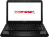
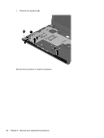
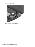
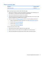
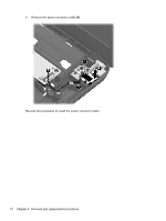
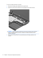
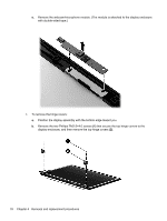
Display assembly This section describes removing the display assembly in its entirety and disassembling all the display subcomponents. If you only need to remove the display bezel, webcam/microphone module, or display panel, you do not need to remove the entire display assembly from the computer. See Display subcomponents (bezel, webcam, panel) on page 39 for more information about removing the display subcomponents that do not require that you remove the entire display assembly from the computer. Description 35.6-cm (14.0-in), HD, LED, BrightView display panel Antennas (includes wireless antenna cables and transceivers; also includes Mylar screw covers) Display bezel for use with Compaq Presario CQ45 models (includes Mylar screw covers) Display bezel for use with HP 1000 models (includes Mylar screw covers) Display cable (includes display panel cable and webcam/microphone cable; also includes Mylar screw covers) Display enclosure for use with Compaq Presario CQ45 models (includes Mylar screw covers) Display enclosure for use with HP 1000 models (includes Mylar screw covers) Hinge covers (includes Mylar screw covers) Hinges (includes Mylar screw covers) HP VGA webcam/microphone module Rubber display bumpers Spare part number 685101-001 685076-001 685082-001 685081-001 685083-001 685078-001 685077-001 685088-001 685090-001 685112-001 685102-001 Before removing the display assembly in its entirety, follow these steps: 1. Shut down the computer. If you are unsure whether the computer is off or in Hibernation, turn the computer on, and then shut it down through the operating system. 2. Disconnect all external devices connected to the computer. 3. Disconnect the power from the computer by first unplugging the power cord from the AC outlet and then unplugging the AC adapter from the computer. 4. Remove the battery (see Battery on page 38). 5. Disconnect the WLAN module antenna cables from the WLAN module (see WLAN module on page 46). 6. Remove the following components: ● Hard drive (see Hard drive on page 50) ● Keyboard (see Keyboard on page 56) ● Top cover (see Top cover on page 59) ● USB board (see USB board on page 69) ● Power connector cable (see Power connector cable on page 71) Component replacement procedures 73
-
 1
1 -
2
-
3
-
4
-
5
-
6
-
7
-
8
-
9
-
10
-
11
-
12
-
13
-
14
-
15
-
16
-
17
-
18
-
19
-
20
-
21
-
22
-
23
-
24
-
25
-
26
-
27
-
28
-
29
-
30
-
31
-
32
-
33
-
34
-
35
-
36
-
37
-
38
-
39
-
40
-
41
-
42
-
43
-
44
-
45
-
46
-
47
-
48
-
49
-
50
-
51
-
52
-
53
-
54
-
55
-
56
-
57
-
58
-
59
-
60
-
61
-
62
-
63
-
64
-
65
-
66
-
67
-
68
-
69
-
70
-
71
-
72
-
73
-
74
-
75
-
 76
76 -
 77
77 -
 78
78 -
 79
79 -
 80
80 -
 81
81 -
 82
82 -
 83
83 -
 84
84 -
 85
85 -
 86
86 -
87
-
88
-
89
-
90
-
91
-
92
-
93
-
94
-
95
-
96
-
97
-
98
-
99
-
100
-
101
-
102
-
103
-
104
-
105
-
106
-
107
-
108
-
109
-
110
-
111
-
112
-
113
-
114
-
115
-
116
-
117
-
118
-
119
-
120
-
121
-
122
-
123
-
124
-
125
-
126
-
127
-
128
 |
 |