Compaq Presario CQ57-300 Presario CQ57 Notebook PC Maintenance and Service Gui - Page 85
detach it., system board components, it may be necessary to move the heat sink from side to side
 |
View all Compaq Presario CQ57-300 manuals
Add to My Manuals
Save this manual to your list of manuals |
Page 85 highlights
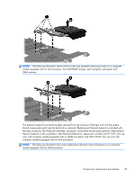
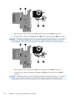
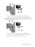
● Display assembly (see Display assembly on page 64) ● System board (see System board on page 71) Remove the fan/heat sink assembly: 1. Disconnect the fan cable from the system board. 2. Turn the system board upside down, with the front toward you. 3. Loosen the captive screws (1) that secure the fan/heat sink assembly to the system board. NOTE: The number of screws used to secure the fan/heat sink assembly to the system board varies by computer model. NOTE: Due to the adhesive quality of the thermal material located between the heat sink and system board components, it may be necessary to move the heat sink from side to side to detach it. 4. Remove the fan and heat sink (2). NOTE: The following illustration shows the fan/heat sink assembly removal process on a computer model equipped with an AMD processor. Component replacement procedures 77
-
 1
1 -
2
-
3
-
4
-
5
-
6
-
7
-
8
-
9
-
10
-
11
-
12
-
13
-
14
-
15
-
16
-
17
-
18
-
19
-
20
-
21
-
22
-
23
-
24
-
25
-
26
-
27
-
28
-
29
-
30
-
31
-
32
-
33
-
34
-
35
-
36
-
37
-
38
-
39
-
40
-
41
-
42
-
43
-
44
-
45
-
46
-
47
-
48
-
49
-
50
-
51
-
52
-
53
-
54
-
55
-
56
-
57
-
58
-
59
-
60
-
61
-
62
-
63
-
64
-
65
-
66
-
67
-
68
-
69
-
70
-
71
-
72
-
73
-
74
-
75
-
76
-
77
-
78
-
79
-
 80
80 -
 81
81 -
 82
82 -
 83
83 -
 84
84 -
 85
85 -
 86
86 -
 87
87 -
 88
88 -
 89
89 -
 90
90 -
91
-
92
-
93
-
94
-
95
-
96
-
97
-
98
-
99
-
100
-
101
-
102
-
103
-
104
-
105
-
106
-
107
-
108
-
109
-
110
-
111
-
112
-
113
-
114
-
115
-
116
-
117
 |
 |
