Compaq Presario CQ57-300 Presario CQ57 Notebook PC Maintenance and Service Gui - Page 91
The gold triangle, straight up, and then remove it.
 |
View all Compaq Presario CQ57-300 manuals
Add to My Manuals
Save this manual to your list of manuals |
Page 91 highlights
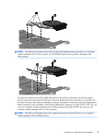
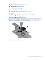
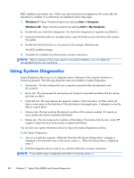
● WLAN module (see WLAN module on page 43) ● Keyboard (see Keyboard on page 49) ● Top cover (see Top cover on page 52) ● System board (see System board on page 71) ● Fan and heat sink (see Fan/heat sink assembly on page 76) Remove the processor: 1. Use a flat-bladed screw driver to turn the processor locking screw one-half turn counterclockwise (1), until you hear a click. 2. Lift the processor (2) straight up, and then remove it. NOTE: The gold triangle (3) on the processor must be aligned with the triangle icon (4) embossed on the processor socket when you install the processor. Reverse this procedure to install the processor. Component replacement procedures 83
-
 1
1 -
2
-
3
-
4
-
5
-
6
-
7
-
8
-
9
-
10
-
11
-
12
-
13
-
14
-
15
-
16
-
17
-
18
-
19
-
20
-
21
-
22
-
23
-
24
-
25
-
26
-
27
-
28
-
29
-
30
-
31
-
32
-
33
-
34
-
35
-
36
-
37
-
38
-
39
-
40
-
41
-
42
-
43
-
44
-
45
-
46
-
47
-
48
-
49
-
50
-
51
-
52
-
53
-
54
-
55
-
56
-
57
-
58
-
59
-
60
-
61
-
62
-
63
-
64
-
65
-
66
-
67
-
68
-
69
-
70
-
71
-
72
-
73
-
74
-
75
-
76
-
77
-
78
-
79
-
80
-
81
-
82
-
83
-
84
-
85
-
 86
86 -
 87
87 -
 88
88 -
 89
89 -
 90
90 -
 91
91 -
 92
92 -
 93
93 -
 94
94 -
 95
95 -
 96
96 -
97
-
98
-
99
-
100
-
101
-
102
-
103
-
104
-
105
-
106
-
107
-
108
-
109
-
110
-
111
-
112
-
113
-
114
-
115
-
116
-
117
 |
 |

●
WLAN module (see
WLAN module
on page
43
)
●
Keyboard (see
Keyboard
on page
49
)
●
Top cover (see
Top cover
on page
52
)
●
System board (see
System board
on page
71
)
●
Fan and heat sink (see
Fan/heat sink assembly
on page
76
)
Remove the processor:
1.
Use a flat-bladed screw driver to turn the processor locking screw one-half turn
counterclockwise
(1)
, until you hear a click.
2.
Lift the processor
(2)
straight up, and then remove it.
NOTE:
The gold triangle
(3)
on the processor must be aligned with the triangle icon
(4)
embossed on the processor socket when you install the processor.
Reverse this procedure to install the processor.
Component replacement procedures
83