Compaq Pro 4300 Pro 4300 All-in-One Business PC - Page 15
CAUTION, Identifying SODIMM Locations
 |
View all Compaq Pro 4300 manuals
Add to My Manuals
Save this manual to your list of manuals |
Page 15 highlights
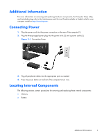
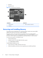
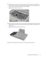
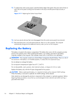
In addition, the computer supports: ● 512-Mbit, 1-Gbit, and 2-Gbit non-ECC memory technologies ● single-sided and double-sided SODIMMS ● SODIMMs constructed with x8 and x16 devices; SODIMMs constructed with x4 SDRAM are not supported NOTE: The system will not operate properly if you install unsupported SODIMMs. The system will automatically operate in single channel mode, dual channel mode, or flex mode, depending on how the SODIMMs are installed. Refer to the following table to identify the SODIMM channel locations. Table 2-1 Identifying SODIMM Locations Location System Board Label Channel Lower Socket DIMM0 Channel B Upper Socket DIMM0 Channel A ● The system will operate in single channel mode if the SODIMM sockets are populated in one channel only. ● The system will operate in a higher-performing dual channel mode if the memory capacity of the SODIMM in Channel A is equal to the memory capacity of the SODIMM in Channel B. ● The system will operate in flex mode if the memory capacity of the SODIMM in Channel A is not equal to the memory capacity of the SODIMM in Channel B. In flex mode, the channel populated with the least amount of memory describes the total amount of memory assigned to dual channel and the remainder is assigned to single channel. If one channel will have more memory than the other, the larger amount should be assigned to channel A. ● In any mode, the maximum operational speed is determined by the slowest SODIMM in the system. There are two memory sockets on the system board located behind the memory access panel. To remove or install memory modules: 1. Remove all removable media, such as compact discs or USB flash drives, from the computer. 2. Turn off the computer properly through the operating system, then turn off any external devices. 3. Disconnect the power cord from the power outlet and disconnect any external devices. CAUTION: You must disconnect the power cord and wait approximately 30 seconds for the power to drain before adding or removing memory modules. Regardless of the power-on state, voltage is always supplied to the memory modules as long as the computer is plugged into an active AC outlet. Adding or removing memory modules while voltage is present may cause irreparable damage to the memory modules or system board. 4. Remove/disengage any security devices that prohibit opening the computer. 5. Place the computer face down on a soft flat surface. HP recommends that you set down a blanket, towel, or other soft cloth to protect the screen surface from scratches or other damage. Removing and Installing Memory 9
-
 1
1 -
2
-
3
-
4
-
5
-
6
-
7
-
8
-
9
-
 10
10 -
 11
11 -
 12
12 -
 13
13 -
 14
14 -
 15
15 -
 16
16 -
 17
17 -
 18
18 -
 19
19 -
 20
20 -
21
-
22
-
23
-
24
-
25
-
26
-
27
-
28
-
29
-
30
-
31
-
32
-
33
-
34
-
35
-
36
-
37
-
38
-
39
-
40
-
41
-
42
 |
 |