Compaq dx7500 Hardware Reference Guide - dx7500 Microtower Model
Compaq dx7500 - Microtower PC Manual
 |
View all Compaq dx7500 manuals
Add to My Manuals
Save this manual to your list of manuals |
Compaq dx7500 manual content summary:
- Compaq dx7500 | Hardware Reference Guide - dx7500 Microtower Model - Page 1
Hardware Reference Guide - dx7500 Microtower Model HP Compaq Business PC - Compaq dx7500 | Hardware Reference Guide - dx7500 Microtower Model - Page 2
Windows, and Windows Vista are either trademarks or registered trademarks of Microsoft Corporation in the United States and/or other countries. The only warranties for HP products and services Company. Hardware Reference Guide HP Compaq Business PC dx7500 Microtower Model First Edition (August 2008) - Compaq dx7500 | Hardware Reference Guide - dx7500 Microtower Model - Page 3
About This Book This guide provides basic information for upgrading this computer model. WARNING! Text set off in this manner indicates that failure to follow directions could result in bodily harm or loss of life. - Compaq dx7500 | Hardware Reference Guide - dx7500 Microtower Model - Page 4
iv About This Book ENWW - Compaq dx7500 | Hardware Reference Guide - dx7500 Microtower Model - Page 5
Product Features Standard Configuration Features ...1 Serviceability Features ...1 Front Panel Components ...2 Media Card Reader Components ...3 Rear Panel Components ...4 Keyboard ...5 Using the Windows Logo Key 5 Serial Number Location ...7 2 Hardware Upgrades Warnings and Cautions ...8 Removing - Compaq dx7500 | Hardware Reference Guide - dx7500 Microtower Model - Page 6
Appendix B Battery Replacement Appendix C External Security Devices Installing a Security Lock ...44 Cable Lock ...44 Padlock ...45 HP Business PC Security Lock 45 Appendix D Electrostatic Discharge Preventing Electrostatic Damage ...48 Grounding Methods ...48 Appendix E Computer Operating - Compaq dx7500 | Hardware Reference Guide - dx7500 Microtower Model - Page 7
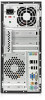
only). Instructions for using the utility are provided in the Troubleshooting Guide. Figure 1-1 HP Compaq dx7500 Microtower NOTE: The drive configuration shown above may be different than your computer model. The illustration shown above may look different than your computer model. Serviceability - Compaq dx7500 | Hardware Reference Guide - dx7500 Microtower Model - Page 8
Light 2 Optical Drive Activity Lights 7 Optical Drive Eject Buttons 3 3.5-inch Media Card Reader (optional)2 8 Headphone Connector 4 Microphone Connector 9 USB (Universal Serial Bus) 2.0 Ports 5 Dual-State Power Button 10 1394 Port 1 Some models have bezel blanks covering one or both - Compaq dx7500 | Hardware Reference Guide - dx7500 Microtower Model - Page 9
I/II ● CompactFlash Card Type 1 ● CompactFlash Card Type 2 ● MicroDrive 7 MS PRO/MS PRO DUO ● Memory Stick (MS) ● Memory Stick Select ● Memory Stick PRO ● MagicGate Memory Stick (MG) ● Memory Stick Duo (MS Duo) Duo (MS PRO Duo) ● Memory Stick PRO- ● MagicGate Memory ● Memory Stick PRO HG - Compaq dx7500 | Hardware Reference Guide - dx7500 Microtower Model - Page 10
Cord Connector 8 PS/2 Mouse Connector (green) 2 Voltage Select Switch 9 Line-Out Connector for powered audio devices (green) 3 Line-In Audio Connector (blue) 10 Microphone Connector (pink) 4 RJ-45 Network Connector 11 Universal Serial Bus (USB) Ports 5 1394 Port 12 DVI Monitor Connector - Compaq dx7500 | Hardware Reference Guide - dx7500 Microtower Model - Page 11
the application software you are Windows Logo key. Table 1-5 Windows Logo Key Functions The following Windows Logo Key functions are available in Microsoft Windows XP and Microsoft Windows Vista. Windows Logo Key Displays or hides the Start menu Windows Logo Key + d Displays the Desktop Windows - Compaq dx7500 | Hardware Reference Guide - dx7500 Microtower Model - Page 12
if you are not connected to a network domain Windows Logo Key + r Launches the Run dialog box Windows Logo Key + u Launches the Utility Manager Windows Logo Key + Pause/Break Launches the System Properties dialog box Windows Logo Key + Tab Windows XP - Cycles through the Taskbar buttons - Compaq dx7500 | Hardware Reference Guide - dx7500 Microtower Model - Page 13
number and product ID number that are located on the upper left side of the computer. Keep these numbers available for use when contacting customer service for assistance. Figure 1-6 Serial Number and Product ID Location ENWW Serial Number Location 7 - Compaq dx7500 | Hardware Reference Guide - dx7500 Microtower Model - Page 14
upgrades be sure to carefully read all of the applicable instructions, cautions, and warnings in this guide. WARNING! To reduce the risk of personal injury from electrical shock, hot surfaces, or fire: Disconnect the power network interface controller (NIC) receptacles. Do not disable the power cord - Compaq dx7500 | Hardware Reference Guide - dx7500 Microtower Model - Page 15
state, voltage is always present on the system board as long as the system is plugged into an active AC outlet. You must disconnect the power cord to avoid damage to the internal components of the computer. 5. Remove the screw (1) that secures the access panel to the computer chassis. 6. Slide the - Compaq dx7500 | Hardware Reference Guide - dx7500 Microtower Model - Page 16
hole for the screw is aligned with the hole in the chassis and tighten the screw (2). Figure 2-2 Replacing the Computer Access Panel 10 Chapter 2 Hardware Upgrades ENWW - Compaq dx7500 | Hardware Reference Guide - dx7500 Microtower Model - Page 17
state, voltage is always present on the system board as long as the system is plugged into an active AC outlet. You must disconnect the power cord to avoid damage to the internal components of the computer. 5. Remove the computer access panel. 6. Press outward on the three latches on the right - Compaq dx7500 | Hardware Reference Guide - dx7500 Microtower Model - Page 18
covering the 3.5-inch and 5.25-inch external drive bays that need to be removed before installing a drive. To remove a bezel blank: 1. Follow the instructions described in Removing the Front Bezel on page 11. 2. Press the two retaining tabs towards the outer left edge of the bezel (1) and pull the - Compaq dx7500 | Hardware Reference Guide - dx7500 Microtower Model - Page 19
Replacing the Front Bezel Insert the three hooks on the left side of the bezel into the slots on the chassis (1) and rotate the bezel on from left to right (2) so that it snaps in place. Figure 2-5 Replacing the Front Bezel ENWW Replacing the Front Bezel 13 - Compaq dx7500 | Hardware Reference Guide - dx7500 Microtower Model - Page 20
, 1Gbit, and 2Gbit non-ECC memory technologies ● single-sided and double-sided DIMMs ● DIMMs constructed with x8 and x16 DDR devices; DIMMs constructed with x4 SDRAM are not supported NOTE: The system will not operate properly if you install unsupported DIMMs. 14 Chapter 2 Hardware Upgrades ENWW - Compaq dx7500 | Hardware Reference Guide - dx7500 Microtower Model - Page 21
are populated in one channel only. ● The system will operate in a higher-performing dual channel mode if the total memory capacity of the DIMMs in Channel A is equal to the total memory capacity of the DIMMs in Channel B. The technology and device width can vary between the channels. For example, if - Compaq dx7500 | Hardware Reference Guide - dx7500 Microtower Model - Page 22
in the system. Installing DIMMs CAUTION: You must disconnect the power cord and wait approximately 30 seconds for the power to drain before adding or removing memory modules. Regardless of the power-on state, voltage is always supplied to the memory modules as long as the computer is plugged into an - Compaq dx7500 | Hardware Reference Guide - dx7500 Microtower Model - Page 23
install any additional modules. 10. Replace the computer access panel. 11. Reconnect the power cord and any external devices, then turn on the computer. The computer should automatically recognize the additional memory when you turn on the computer. 12. Lock any security devices that were disengaged - Compaq dx7500 | Hardware Reference Guide - dx7500 Microtower Model - Page 24
expansion cards. power-on state, voltage is always present on the system board as long as the system is plugged into an active AC outlet. You must disconnect the power cord to avoid damage to the internal components of the computer. 5. Remove the computer access panel. 18 Chapter 2 Hardware Upgrades - Compaq dx7500 | Hardware Reference Guide - dx7500 Microtower Model - Page 25
board and the corresponding expansion slot on the back of the computer chassis. 7. On the rear of the computer, a slot cover lock secures the expansion card brackets in place. Remove the screw from the slot cover lock then slide the slot cover lock up to remove it from the chassis. Figure - Compaq dx7500 | Hardware Reference Guide - dx7500 Microtower Model - Page 26
are removing a PCI Express x1 card, hold the card at each end and carefully rock it back and forth until the connectors pull free from the socket. Be sure not to scrape the card against the other components. Figure 2-11 Removing a PCI Express x1 Expansion Card 20 Chapter 2 Hardware Upgrades ENWW - Compaq dx7500 | Hardware Reference Guide - dx7500 Microtower Model - Page 27
pull free from the socket. Be sure not to scrape the card against the other components. Figure 2-12 Removing a PCI Express x16 Expansion Card 9. Store the removed card in anti-static packaging. 10. If you are not installing a new expansion card, install an expansion slot cover to close the open slot - Compaq dx7500 | Hardware Reference Guide - dx7500 Microtower Model - Page 28
card toward the rear of the chassis so that the bottom of the bracket on the card slides into the small slot on the chassis. Press the card removed. Figure 2-14 Securing the Expansion Cards and Slot Covers 13. Connect external cables to the installed card, if needed. Connect internal cables to - Compaq dx7500 | Hardware Reference Guide - dx7500 Microtower Model - Page 29
15. Reconnect the power cord and any external devices, then turn on the computer. 16. Lock any security devices that were disengaged when the access panel was removed. 17. Reconfigure the computer, if necessary. Refer to the Computer Setup (F10) Utility Guide for instructions on using Computer Setup - Compaq dx7500 | Hardware Reference Guide - dx7500 Microtower Model - Page 30
labeled FLOPPY. ● Connect a media card reader to the USB connector labeled F_USB2. ● The system does not support Parallel ATA (PATA) optical drives or other drives use M3 metric screws. The HP-supplied M3 metric guide screws (1) are black. The HP-supplied 6-32 standard screws (2) are silver. - Compaq dx7500 | Hardware Reference Guide - dx7500 Microtower Model - Page 31
: If you are inserting or removing a drive, shut down the operating system properly, turn off the computer, and unplug the power cord. Do not remove a drive while the computer No. System Board Connector System Board Label 1 Media Card Reader 2 SATA4 3 SATA5 4 SATA1 F_USB2 SATA4 SATA5 - Compaq dx7500 | Hardware Reference Guide - dx7500 Microtower Model - Page 32
the power cord to avoid damage to the internal components of the computer. 5. Remove the access panel and front bezel. 6. Disconnect the power cable (1) and data cable (2) from the rear of the optical drive. Figure 2-18 Disconnecting the Power and Data Cables 26 Chapter 2 Hardware Upgrades ENWW - Compaq dx7500 | Hardware Reference Guide - dx7500 Microtower Model - Page 33
state, voltage is always present on the system board as long as the system is plugged into an active AC outlet. You must disconnect the power cord to avoid damage to the internal components of the computer. 5. Remove the access panel and front bezel. 6. If you are installing a drive in a bay - Compaq dx7500 | Hardware Reference Guide - dx7500 Microtower Model - Page 34
. 11. Connect the power cable (1) and data cable (2) to the rear of the optical drive. Figure 2-21 Connecting the Power and Data Cables 12. Replace the front bezel and access panel. 13. Reconnect the power cord and turn on the computer - Compaq dx7500 | Hardware Reference Guide - dx7500 Microtower Model - Page 35
The 3.5-inch drive bay may contain a diskette drive or a media card reader. 1. Remove/disengage any security devices that prohibit opening the computer system is plugged into an active AC outlet. You must disconnect the power cord to avoid damage to the internal components of the computer. 5. Remove - Compaq dx7500 | Hardware Reference Guide - dx7500 Microtower Model - Page 36
removing a media card reader, disconnect the USB cable from the system board. Figure 2-23 Disconnecting the Media Card Reader Cable 7. Remove and out of the bay (2). Figure 2-24 Removing a 3.5-inch Device (Media Card Reader Shown) NOTE: To install an external 3.5-inch drive, refer to Installing - Compaq dx7500 | Hardware Reference Guide - dx7500 Microtower Model - Page 37
the system is plugged into an active AC outlet. You must disconnect the power cord to avoid damage to the internal components of the computer. 5. Remove panel and front bezel. 6. If you are installing a diskette drive or media card reader in a bay covered by a bezel blank, remove the front bezel then - Compaq dx7500 | Hardware Reference Guide - dx7500 Microtower Model - Page 38
power and data cables to the rear of the drive and connect the other end of the data cable to the connector on the system board labeled FLOPPY. b. If installing a media card reader, connect the USB cable from the media card system, software drivers, and any software applications that were preinstalled on - Compaq dx7500 | Hardware Reference Guide - dx7500 Microtower Model - Page 39
the side of the hard drive cage (1), then slide the hard drive cage away from the bottom of the chassis (2) as shown below. Figure 2-27 Releasing the Hard Drive Cage ENWW Installing Additional Drives 33 - Compaq dx7500 | Hardware Reference Guide - dx7500 Microtower Model - Page 40
8. Lift the hard drive cage out of the chassis. Figure 2-28 Removing the Hard Drive Cage 9. Disconnect the power cable (1) and data cable (2) from the back of the hard drive. Figure 2-29 Disconnecting the Hard Drive Cables 34 Chapter 2 Hardware Upgrades ENWW - Compaq dx7500 | Hardware Reference Guide - dx7500 Microtower Model - Page 41
10. Remove the four screws that secure the hard disk drive to the hard drive cage (1), then slide the hard disk drive out of the hard drive cage (2). Figure 2-30 Removing the Hard Drive NOTE: To install an internal 3.5-inch hard drive, refer to Installing an Internal 3.5-inch Hard Drive on page 35. - Compaq dx7500 | Hardware Reference Guide - dx7500 Microtower Model - Page 42
Drives on page 24 for an illustration of the retainer screws location. Figure 2-31 Installing the Hard Drive in the Drive Cage 36 Chapter 2 Hardware Upgrades ENWW - Compaq dx7500 | Hardware Reference Guide - dx7500 Microtower Model - Page 43
3. Connect the power cable (1) and data cable (2) to the back of the hard drive. Figure 2-32 Connecting the Hard Drive Cables CAUTION: Never crease or bend a SATA data - Compaq dx7500 | Hardware Reference Guide - dx7500 Microtower Model - Page 44
SATA0 to avoid any hard drive performance problems. If you are adding a second hard the computer access panel. 8. Reconnect the power cord and any external devices, then software drivers, and any software applications that were preinstalled on the computer. 38 Chapter 2 Hardware Upgrades ENWW - Compaq dx7500 | Hardware Reference Guide - dx7500 Microtower Model - Page 45
A Specifications Table A-1 Specifications Desktop Dimensions Height 14.76 in 37.5 cm Width 6.98 in Maximum 1575 BTU/hr 397 kg-cal/hr Typical (idle) 307 BTU/hr 77 kg-cal/hr Power Supply 115V 230V Operating Voltage Range1 90-132 VAC 180-264 VAC Rated Voltage Range 100-127 VAC 200- - Compaq dx7500 | Hardware Reference Guide - dx7500 Microtower Model - Page 46
Table A-1 Specifications (continued) Rated Input Current (maximum)1 8A @ 100 VAC 4A @ 200 VAC 1 This system utilizes a passive power factor corrected power supply. The power factor correction is present in the 230V operating mode only. This allows the system to pass the CE mark requirements for - Compaq dx7500 | Hardware Reference Guide - dx7500 Microtower Model - Page 47
will be cleared. Refer to the Computer Setup (F10) Utility Guide for information on backing up the CMOS settings. Static electricity can the computer is NOT connected to AC power. HP encourages customers to recycle used electronic hardware, HP original print cartridges, and rechargeable batteries. - Compaq dx7500 | Hardware Reference Guide - dx7500 Microtower Model - Page 48
the type of battery holder on the system board, complete the following instructions to replace the battery. Type 1 a. Lift the battery out of its automatically secures the battery in the proper position. Type 2 a. To release the battery from its holder, squeeze the metal clamp that extends above - Compaq dx7500 | Hardware Reference Guide - dx7500 Microtower Model - Page 49
replaced, use the following steps to complete this procedure. 8. Replace the computer access panel. 9. Plug in the computer and turn on power to the computer. 10. Reset the date and time, your passwords, and any special system setups using Computer Setup. Refer to the Computer Setup (F10) Utility - Compaq dx7500 | Hardware Reference Guide - dx7500 Microtower Model - Page 50
C External Security Devices NOTE: For information on data security features, refer to the Computer Setup (F10) Utility Guide and the Desktop Management Guide. Installing a Security Lock The security locks displayed below and on the following pages can be used to secure the computer. Cable Lock - Compaq dx7500 | Hardware Reference Guide - dx7500 Microtower Model - Page 51
Padlock Figure C-2 Installing a Padlock HP Business PC Security Lock 1. Fasten the security cable by looping it around a stationary object. Figure C-3 Securing the Cable to a Fixed Object ENWW Installing a Security Lock 45 - Compaq dx7500 | Hardware Reference Guide - dx7500 Microtower Model - Page 52
2. Thread the keyboard and mouse cables through the lock. Figure C-4 Threading the Keyboard and Mouse Cables 3. Screw the lock to the chassis using the screw provided. Figure C-5 Attaching the Lock to the Chassis 46 Appendix C External Security Devices ENWW - Compaq dx7500 | Hardware Reference Guide - dx7500 Microtower Model - Page 53
4. Insert the plug end of the security cable into the lock (1) and push the button in (2) to engage the lock. Use the key provided to disengage the lock. Figure C-6 Engaging the Lock ENWW Installing a Security Lock 47 - Compaq dx7500 | Hardware Reference Guide - dx7500 Microtower Model - Page 54
mat. If you do not have any of the suggested equipment for proper grounding, contact an HP authorized dealer, reseller, or service provider. NOTE: For more information on static electricity, contact an HP authorized dealer, reseller, or service provider. 48 Appendix D Electrostatic Discharge ENWW - Compaq dx7500 | Hardware Reference Guide - dx7500 Microtower Model - Page 55
front of the desktop unit as this also restricts airflow. ● Never operate the computer with the access panel or any of the expansion card slot covers type of material. ● Install or enable power management functions of the operating system or other software, including sleep states. ● Turn off the - Compaq dx7500 | Hardware Reference Guide - dx7500 Microtower Model - Page 56
temperature, as condensation may form inside the unit. If the temperature suddenly Cleaning ● Clean the panel and controls with a soft, dry cloth or it checked by an authorized HP service provider. Shipping Preparation Follow these drive locks automatically when the system power is turned off. 2. Remove and - Compaq dx7500 | Hardware Reference Guide - dx7500 Microtower Model - Page 57
ENWW locks cable lock 44 HP Business PC Security Lock 45 padlock 45 M media card reader features 3 installing 31 removing 29 memory installing 14 populating sockets 15 specifications 14 microphone connector 2, 4 monitor connector DVI 4 VGA 4 mouse connector 4 N network connector 4 O optical drive - Compaq dx7500 | Hardware Reference Guide - dx7500 Microtower Model - Page 58
reader 29 optical drive 26 PCI Express x1 card 20 PCI Express x16 card 21 S security cable lock 44 HP Business PC Security Lock 45 padlock 45 serial number location 7 serviceability features 1 shipping preparation 50 specifications computer 39 memory 14 system board drive connections 25 U unlocking
-
 1
1 -
 2
2 -
 3
3 -
 4
4 -
 5
5 -
 6
6 -
 7
7 -
8
-
9
-
10
-
11
-
12
-
13
-
14
-
15
-
16
-
17
-
18
-
19
-
20
-
21
-
22
-
23
-
24
-
25
-
26
-
27
-
28
-
29
-
30
-
31
-
32
-
33
-
34
-
35
-
36
-
37
-
38
-
39
-
40
-
41
-
42
-
43
-
44
-
45
-
46
-
47
-
48
-
49
-
50
-
51
-
52
-
53
-
54
-
55
-
56
-
57
-
58
 |
 |

Hardware Reference Guide - dx7500
Microtower Model
HP Compaq Business PC