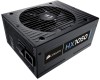
Corsair CMPSU-1050HX User Manual - Page 7
Installation - cmpsu
 |
View all Corsair CMPSU-1050HX manuals
Add to My Manuals
Save this manual to your list of manuals |
Page 7 highlights
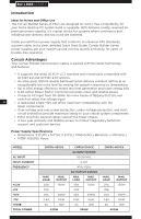
Package Contents • Corsair Builder Series power supply unit • User Manual • AC power cord • Cable ties • Mounting screws • Corsair case badge Corsair Cable Configuration CMPSU-430CX QTY Length Connectors/cable 1 600mm 1 1 600mm 1 1 600mm 1 2 550mmmm 2 1 850mm 4 B U I L D E R S E R I E S™ ATX Cable (24-pin) EPS12V CPU Cable (8-pin) PCI-E Cable SATA Cable Peripherial Cable QTY 1 1 2 1 1 1 CMPSU-500CX Length Connectors/cable 600mm 1 600mm 1 600mm 1 550mm 2 700mm 3 1050mm 5 ATX Cable (24-pin) EPS12V CPU Cable (8-pin) 7 PCI-E Cable SATA Cable Peripherial Cable QTY 1 1 2 2 1 CMPSU-600CX Length Connectors/cable 600mm 1 600mm 1 600mm 1 700mm 3 1050mm 5 ATX Cable (24-pin) EPS12V CPU Cable (8-pin) PCI-E Cable SATA Cable Peripherial Cable NOTES: • Floppy connectors are attached to the end of the peripheral cable. • The ATX power connector has a detachable four-pin mechanism in order to support either a 24-pin or a 20-pin socket on the motherboard. • The EPS12V power connector has a detachable four-pin mechanism in order to support either an eight-pin socket or a four-pin "P4/12V" socket on the motherboard. Installation Before proceeding with installation, please read this manual in its entirety. Step A: Removing your existing power supply If you are building a new system, skip to Step B.
-
 1
1 -
 2
2 -
 3
3 -
 4
4 -
 5
5 -
 6
6 -
 7
7 -
 8
8 -
 9
9 -
 10
10 -
 11
11 -
 12
12 -
13
-
14
-
15
-
16
-
17
-
18
-
19
-
20
-
21
-
22
-
23
-
24
-
25
-
26
-
27
-
28
-
29
-
30
-
31
-
32
-
33
-
34
-
35
-
36
-
37
-
38
-
39
-
40
-
41
-
42
-
43
-
44
-
45
-
46
-
47
-
48
-
49
-
50
-
51
-
52
-
53
-
54
-
55
-
56
-
57
-
58
-
59
-
60
 |
 |
