Craftsman 21239 Operation Manual - Page 17
Ia,warning
 |
View all Craftsman 21239 manuals
Add to My Manuals
Save this manual to your list of manuals |
Page 17 highlights
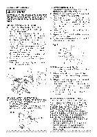
3. Ifthedesireadngliesoneoftheninepositive SETTINCGUTTINDGEPT(HFIGS. ) stopsre, leastheepositivsetoplockinlegver, Thedeptohfcutcanbepresefot revenand mthaeknsienscguurrbetehyteilgehvteesrnniatnhpgeisnmtoipteohrsaintiodanlen,.d r1e.pAedtjiutistsvhhteeaclulotctwiunhtgse.adow(nSeeCUTTING 4. Inftihneepmoisteiatirvnsetgoldepesss,imirepisdloyncokotthneemofittheterable aHttEhAedsDeescitrieoddunen)pttitlhh.eteetohfthebladaere icnlotopckowsiidtsiioebrenytcutrionnin.tghemitehrandilnethe 2.Whilheoldinthgeuppearrminthapt osition, tpularntthe(2es).topknob(1)untilttouchethsestop FigQ. 3. Rechetchkebladdeeptbhymovinthge cmuotttiinohognefaatyfdrpoinctatcobul ataclotkhntrghoeucgothnetfruaollrlm. ._..t._. ._s_ MITESRCALIENDICATAODRJUSTMENT (FIGQ, } 2 1. Movtehetablteothe0°positivsetop. 2. Loosethnescrew(4)thaht oldtsheindicator withaPhillipsscrewdriver. ADJUSTING CUTTING DEPTH (FIG. S) The maximum depth travel of the cutting head 3.Aredtjiugshthttseeicnnrdeiwca. t(o3r)tothe0°maraknd was set at the factory. Check to see that the blade does not extend more than 1/4 in. below the table insert, and does not touch the control ADJUSTIFNEGNCSEQUAREN(EFSIGSR. ) arm throat or any part of the base or table. If the 1. Loosethnethreefencleockinbgolt(s1). 23.. LUoswinaetghrseqcuuattr(ine3ag)rl,amaythnedlhoeckeionlpfthoessiqtiouna.re maximum depth needs readjusting: 1. Loosen the stop knob (1) while moving the cutting head down until the blade extends just againtshtebladaendtheruleargaintshte 1/4 in. below the table insert. fenc(e2)asshown. 4.Adjustht efenc9e0°tothebladaendtighten 2. Adjust the stop knob (1) to touch the stop plate (2). tChAefoUuTfreIOnIfNctlheo:ecskaiwnbhgoalstnso. tbeenused recentlrye,checbkladsequarenetsosthe 3. Recheck the blade depth by moving the cutting head front to back through the full motion of a cut along the control arm. If the fenceand readjust if needed. blade touches the inside of the control arm, 5. After fence has been aligned, using a scrap readjust the setting. piece of wood, make a cut at 90 ° then check squareness on the piece. Readjust if necessary. Fig. R SLIDING THE REAR EXTENSION SUPPORT BAR (FIG. T) IA,WARNING To avoid possible personal injury or damage to the miter saw due to tipping, do not 12 1 operate the saw without the Rear Extension Support Bar. Loosen the two screws (1) and extend the rear extension support bar (2) by sliding it out to match position, tighten the two screws.
-
 1
1 -
2
-
3
-
4
-
5
-
6
-
7
-
8
-
9
-
10
-
11
-
 12
12 -
 13
13 -
 14
14 -
 15
15 -
 16
16 -
 17
17 -
 18
18 -
 19
19 -
 20
20 -
 21
21 -
 22
22 -
23
-
24
-
25
-
26
-
27
-
28
-
29
-
30
-
31
-
32
-
33
-
34
 |
 |
