Craftsman 21514 Operation Manual - Page 4
Attach Table - belt sander
 |
View all Craftsman 21514 manuals
Add to My Manuals
Save this manual to your list of manuals |
Page 4 highlights
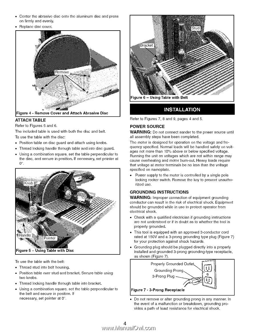
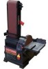
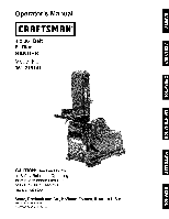
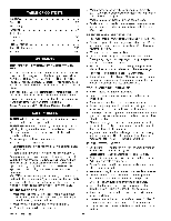
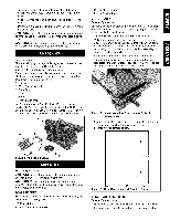
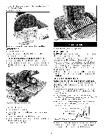
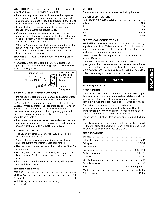
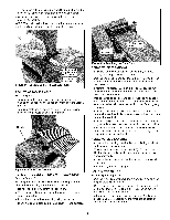
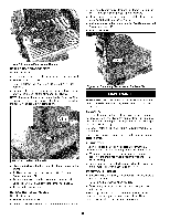
• Center the abrasive disc onto the aluminum disc and press on firmly and evenly. Replace disc cover. Figure 6 - Using Table with Belt Figure 4 - Remove Cover and Attach Abrasive Disc ATTACH TABLE Refer to Figures 5 and 6. The included table is used with both the disc and belt. To use the table with the disc: ° Position table on disc guard and attach using knobs. ° Thread locking handle through table and into disc guard. ° Using a combination square, set the table perpendicular to the disc, and secure in position. If necessary, set pointer at 0 °" Figure 5 - Using Table with Disc To use the table with the belt: ° Thread stud into belt housing. ° Position table over stud and bracket. Secure table using two knobs. ° Thread locking handle through table into bracket. ° Using a combination square, set the table perpendicular to the belt and secure in position. If necessary, set pointer at 0°. Refer to Figures 7, 8 and 9, pages 4 and 5. POWER SOURCE WARNING: Do not connect sander to the power source until all assembly steps have been completed. The motor is designed for operation on the voltage and frequency specified. Normal loads will be handled safely on voltages not more than 10% above or below specified voltage. Running the unit on voltages which are not within range may cause overheating and motor burn-out. Heavy loads require that voltage at motor terminals be no less than the voltage specified on nameplate. ° Power supply to the motor is controlled by a single pole locking rocker switch. Remove the key to prevent unauthorized use. GROUNDING INSTRUCTIONS WARNING: Improper connection of equipment grounding conductor can result in the risk of electrical shock. Equipment should be grounded while in use to protect operator from electrical shock. • Check with a qualified electrician if grounding instructions are not understood or if in doubt as to whether the tool is properly grounded. • This tool is equipped with an approved 3-conductor cord rated at 150V and a 3-prong grounding type plug (Figure 7) for your protection against shock hazards. • Grounding plug should be plugged directly into a properly installed and grounded 3-prong grounding-type receptacle, as shown (Figure 7). Properly Grounded OutleL,,,,,_ _-_ Grounding Prong LL_j' 3-Prong Plug __ Figure 7 - 3-Prong Receptacle • Do not remove or alter grounding prong in any manner. In the event of a malfunction or breakdown, grounding provides a path of least resistance for electrical shock. 4
-
 1
1 -
 2
2 -
 3
3 -
 4
4 -
 5
5 -
 6
6 -
 7
7 -
 8
8 -
 9
9 -
 10
10 -
11
-
12
-
13
-
14
-
15
-
16
-
17
-
18
-
19
-
20
-
21
-
22
-
23
-
24
 |
 |