Craftsman 22401 Operating Instructions - Page 2
instructions, blin g, Opera - blade
 |
View all Craftsman 22401 manuals
Add to My Manuals
Save this manual to your list of manuals |
Page 2 highlights
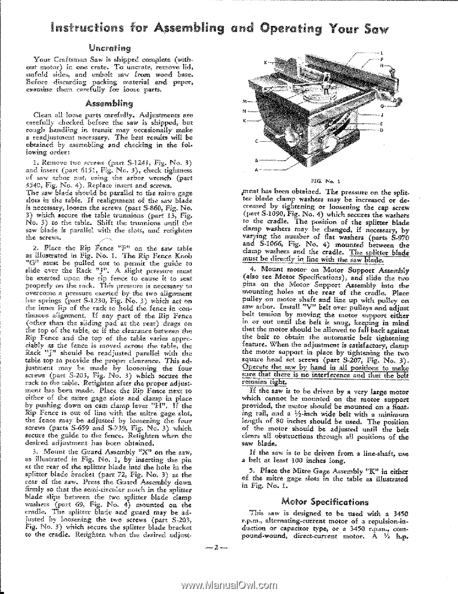
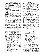
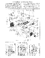
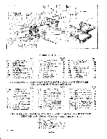
instructions for sem, blin g Qn_ Uncrating Your Craftsman Saw is shipped complete (Mth_ _t motor) in one crate, To uncrate_ remove lid_ unfold sides, and nnboK saw' from wood base, Before discarding packing material and paper_ examine them carefhtly fO_ loose parts. Opera t ,S Your Saw C_ean all 1oose parts carefullyo Adjustments are carefully checked before the saw is shipped_ but rough handling in transk may nccasionMly make a readjustment necessary_ The best results wiil be obtained by assembling and checking in the following order: I. Remove two screws (part So1241_ Fig. No0 3) amd insert (part 615I, Fig:. No,. 3), &eck tightness of saw arbor nut_ using the arbor wrench (part 3540, Fig. No. 4). Replace insert amd screws. The saw blade sbou/d be paralIel to the mitre gage slots in the table. If realignment of the saw blade is necessar B loosen the screws (part: S-860, Fig. No, 3) which secure the table trunnions (part 13_ Fig. No. 3) to the table, Shift the trunnions until the saw blade :s parallel with the slots_ and redghten the screws. 2. Place the Rip Fence ':'F" on the saw table as ill_trated in Fig. No, 1o The Rip Fence Kuob "G" must be pulled out to permit the guide to slide over the Rack "J'L A slight pressure must be exerted upon the rip fence to cause it to seat proper[>" on the rack. This pressure is necessary to overcome a pressure exerted by the two alignment bar springs (part Sd230_ Fig. No. 3.) which act on the inner lip of the rack to hold the {ence in con+ tiuuous al{g_ment. If any part of the Rip Fence Rip Fence and the top of the table varies appreciably as the fence is moved across the: table_ the ha& *_J" should be readjusted parallel with the tame top to provide the proper clearance, This adjustment may be made by loosening the four screws (part S_203_ Fig. No0 3) which secure the rack m the table_ Retighten after the prefer adjustmeat has been made° Place the Rip Fence next to ekber of the mitre gage slots and damp ia place by pushi_g down on cam clamp lever "H'0 If the Rip Fence is out of Iine with the mkre gage slot, the fence may be adjured by loosening the four screws (parts S-659 and S-739, Fig. No, 3) which secure the guide m the feuce, Retlghteu when _e desired adjustment has been obtained. 3, Mount the Guard Assembly "X" on the saw_ as. illustrat_ in Fig. No. 1, by insertlng the pin at the rear of the @ikter blade into the hole in the spNtter blade bracket (part 72, Fig, No_ 3) at the rear of the saw.. Press the Guard Assembly do_ firmly so that the semi-circular notch in the splitter blade slips between the two splitter blade damp washers (part 69, Pig. No,. 4) mounted oa the cradle, _.e splitter blade and guard may be adiusted by tooseuing the two screws (part 8-203_ Fig, No. 3) which secure the splitter blade bra&et to the cradle° Retighten when the desired adjust- 2 FIG. No, I _neat has b_n obtained. The pressure on the split- ter Made damp washers may be incr_sed or de- creased by tightening or loosening the cap screw (part S-I090_ Fig. No. 4) which secures the washers to the cradle. The position of the splitter blade clamp washers may be changed_ if n_essary, by varying the number of flat washers (parts S-970 and S-i066_ Fig, No. 4) mounted between _e damp washers and the cradle, must: be dlrec_ in tlne with the er blade 4_ Mount motor on Motor Support Assembly (also see Motor Specifieations)_ and stlde the _o pins on the Motor Support Ass_b|y _to the mounting holes at the rear of the cradle. Pinch pulley on motor shaft and line up Mth pulley on _aw arbor, Install "V" belt over pulleys and adjust belt tensloa by moving the motor support elth_ in oe out until the belt is snug, keep_g ia mlnd that the motor should be allowed to fall back against the belt to obtain the automatic belt tlghten_g feature. When the adjustment is sadsfactory_ damp the motor support in place by tightening the two square head set screws (part S-207, Fig. No_ 3). If the saw is to be driven by a very large me{or which cannot be mounted on the motor support provided_ the motor should be mounted oa a lions. ing rait_ and a _-inch wide belt Mth a m_im_ length of 80 inch_ should be used. The posltion of the motor should be adjusted until _e belt clears all obstructions saw blade. through all positions of the If the saw is m be driven from a line-shaft_ use a belt at least t00 in&ca long. 5. Place the Mi_e Gage Assembly "K" in tither of the mitre gage slo_ in the table as illustrad in Fig, No. 1. Motor Spe¢ifkations This saw is d_igned to be used with a 3450 r.p,m., alternating.current motor of a repulsion-inductlon or capacitor type_ or a 3450 rop.m,_ corn- direct-current motor. A V2 h.p.
-
 1
1 -
 2
2 -
 3
3 -
 4
4 -
 5
5 -
 6
6
 |
 |