Craftsman 22401 Operating Instructions - Page 3
Operatin9 - dimensions
 |
View all Craftsman 22401 manuals
Add to My Manuals
Save this manual to your list of manuals |
Page 3 highlights
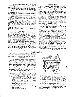
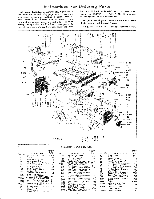
Operatin9 motor is recommended for light: duty, and a ¾ the base of the motor. If this dimension varies appr_iably from four inches, it may be necessary to obtain a belt of a different length° If a 1750 r,p°mo motor is used, a sixdnch motor pul@ and a longer belt must be purch_ed_ These may be ordered through any Sears Retail or Mall Order Store° The arbor has been made ex_a long to accommodate a second pulley to provide for double belt operation, although the single belt is sufficient to _rry the loads normally encountered. The extra motor pulley, arbor pulley, and b,elt may be or- Caution: und_ no circumstances should a six- inch motor' pulley be used with a 3450 r.p.mo motor. _e saw blade speed resulting from such a pulley ratio would be d_gerous° Do not use a three.lnch motor p_ley _th a i750 r.p.mo motor° Such a u_ey ratio will not give sadsfacto_ ormance_ saw p_- Static Elec:tricity Occasionally s slight shock may be experienced upon touching a machine tool, Ti_is is usually due to a stadc decuicai charge built up by the friction between moving parts_ such as the V-belt and pMley. It is not necessarily indicative of a gronnd_ motor or faulty electrical connections, To eliminate this condition, as well as guard against the effe_ og a grounded motor _ faulty' connections, the saw should be grounded to a water or steam pipe. Adjustments 1o All pointers may be readily adjusted to the zero position by loosening the lock screw, resetting the pointer and retlghtening the scr_0 2. Both rip fence indicators (part 135, Fig. No. 3) should be adjusted to zero by placing the rip fence first to the right and then to the left of the saw blade. The teeth of the saw biade should touch the rip fence i@tly when the adjustment is made. to zero Operat_ng_Contro[s the 1. Elevation Hand Wheel "A', on the front of saw, controls devadon of the blade or depth of cut as indicated on the Depth Dial "B'. The Depth Dial should read zero_ with the saw' blade just flush with the surface of the table. Correction of this setting may be made by sliding the Lift Dial Tape. This adjustment will be necessary after the blade _s b_n filed or sharpened, reducing the original diameter, or when a saw blade of a diameter other than 8 inches is used. If an extremely accurate depth of cut is r_uired the height of the saw blade above the table should be measured or_ preferably, a test cut should be made on, a piece of scrap and the actual depth of cut measured. Under no circumstances should a saw blade wi eter greater than I0 inches be _ed with this saw. _-_a_ 10-inch saw blade is used_ the pre_nt 3.1neh motor pulley should be reNa_cxt with a 2½-inch SiZe. 2. Tilt Hand Wheel "C'_ on the left side of the saw, controls the angle of tilt. The saw Made may be tilted from 0 degrees to 45 degrees. _e angle of tilt is indicated on the Tilt Gage _'D'L If the angle of the oa_ (tilt) must be extremely a_urate, the angle of the saw blade sho_x_d be &eck_ with a protractor or with a board which is known to be cut at the exact angle required_ 3. The tilt mechanlsm may be to&ed in any" position by means of Clamp Screw Handle "E" which opiates like a s_ket wrench. The tilt mechanism should always be locked before starting work through the saw and should always be un- locked befor p_ng 4. Rip Pence "F' is operated by pushing in Rip Fence Knob "G" which engages a pinion gear with the teeth on Re& _J"o Turning knob _G" after engagement of the g_r will cause _e Np fence to move easily across the table° When the pinion gear is dis_gaged by pulling out knob _G"_ _e rip fen_ may be moved across the table by hand. After the rip fence has been adjusted to the post. don d_ired, it is. clamped in place by pushing down on Cam Ciamp Lever "H'L if the ciamplng action is too tight or too loose it may' be adjured by in- c:reasL,ag or decr_siug the effective length of the rip fence clamp rod (part 6100, Fig. No. 3). This is accomplished by loosening the sleeve nut (part t40, Fig. Non 3) and readjusting the hex nut (part S-108, Fig. No. 3) on the end of the: clamp rod at the back of the fence. The sleeve nut, which is eroployed as a jam nut, should be redghtened after _e adjustment h_ b_n obtained. A sticky or dirty table or rip fence may prevent the rip fence from maintaining proper alignment. Keeping the saw _ble and rip fence clean and tap#hi the rip fence lightly* to assist the fence to find its natural position Mll be found m help maintain the alignment of _e rip %nee with the saw blade. _ross Cu#Hn$ Before performing cross cutting operations_ the alignment of the mitre gage slots wid_ the saw blade should be checked and corrected, if necessary, described in paragraph ! under Assembling. Mitre Gage "K'is graduated in degrees from the 90 degree position to the 30 degree position, both left and right. The Mitre Clamp Knob _L" locks the mitre gage in any position d_ired_ The Mitre Extension Rods "M" are locked to the mitre gage by Thumb Screws _'N'+ These rods are pro+ vided for use when it is desired to cut severM pieces of work to the same length. To perform accurate work with the mitre gage the Mitre Gage Pointer (part 6285_ Fig. No. 3) must be properly adjusted. The mi_e gage should be set on a _e 90 degree an_e by use of a square by use of the 90 degree relationship between the mitre gage Nots and the front table edge, _e mitre
-
 1
1 -
 2
2 -
 3
3 -
 4
4 -
 5
5 -
 6
6
 |
 |