Craftsman 29918 Owners Manual - Page 6
Tools, Assembly, Position
 |
View all Craftsman 29918 manuals
Add to My Manuals
Save this manual to your list of manuals |
Page 6 highlights
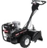
Your new tiller has been assembled at the factory with the exception of those parts left unassembled for shipping purposes. To ensure safe and proper operation of your tiller all parts and hardware you assemble must be tightened securely. Use the correct tools as necessary to insure proper tightness. TOOLS REQUIRED FOR ASSEMBLY A socket wrench set will make assembly easier. Standard wrench sizes are listed. (1) Utility knife (1) Wire cutter (1) Tire pressure (1) Screwdriver (1) Pair of pliers (1) 9/16" wrench gauge OPERATOR'S POSITION When right or left hand is mentioned in this manual, it means when you are in the operating position (standing behind tiller handles). FRONT . Remove packing material from handle assembly. Shift Rod Handle Assembly INSTALL HANDLE . Insert one handle lock (with teeth facing outward) in gearcase notch. (Apply grease on smooth side of handle lock to aid in keeping lock in place until handle assembly is lowered into position.) VIEWED FROM R.H. SIDE OF TILLER LEFT RIGHT _. Handle Assembly Gearcase Notch / H/andle Lock OPERATOR'S POSITION UNPACKING CARTON _ILCAUTION: Be careful of exposed staples when handling or disposing of carton- 2. Grasp handle assembly. Hold in "up" position. Be sure handle lock remains in gearcase notch. Slide handle assembly into position. ing material. IMPORTANT: When unpacking and as- "_')!'_: ' Handle Assembly sembling tiller, be careful not to stretch or kink cables. Position 1. While holding handle assembly, cut cable ties securing handle assembly to top frame. Let handle assembly rest on tiller. 2. Remove top frame of carton. 3. Slowly ease handle assembly place on top of carton. up and Loosen Handle Lock Lever to Move 4. Cut down right hand front and right hand rear corners of carton. Lay side carton wall down. 6
-
 1
1 -
 2
2 -
 3
3 -
 4
4 -
 5
5 -
 6
6 -
 7
7 -
 8
8 -
 9
9 -
 10
10 -
 11
11 -
 12
12 -
13
-
14
-
15
-
16
-
17
-
18
-
19
-
20
-
21
-
22
-
23
-
24
-
25
-
26
-
27
-
28
-
29
-
30
-
31
-
32
-
33
-
34
-
35
-
36
-
37
-
38
-
39
-
40
-
41
-
42
-
43
-
44
-
45
-
46
-
47
-
48
-
49
-
50
-
51
-
52
-
53
-
54
-
55
-
56
-
57
-
58
-
59
-
60
-
61
-
62
-
63
-
64
-
65
-
66
-
67
-
68
-
69
-
70
-
71
-
72
-
73
-
74
-
75
-
76
-
77
-
78
-
79
-
80
-
81
-
82
-
83
-
84
-
85
-
86
-
87
-
88
-
89
-
90
-
91
-
92
-
93
-
94
-
95
-
96
-
97
-
98
-
99
-
100
-
101
-
102
-
103
-
104
 |
 |
