Cub Cadet 528 SWE Two-Stage Snow Thrower 524 WE Operator's Manual - Page 8
Top View
 |
View all Cub Cadet 528 SWE Two-Stage Snow Thrower manuals
Add to My Manuals
Save this manual to your list of manuals |
Page 8 highlights
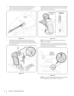
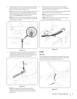
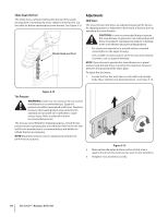
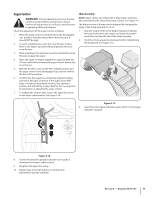
2. Insert chute control rod into chute control head. Push rod as far into chute control head as possible, keeping the holes in the rod pointing upward. See Figure 3-4. 4. Squeeze the trigger on the joystick and rotate the chute by hand to face forward. The holes in the chute control input will be facing up. See Figure 3-6. Chute Control Input Top View Figure 3-4 Figure 3-6 3. Place chute onto chute base and ensure chute control NOTE: The chute will not rotate without squeezing the rod is positioned under the handle panel. Install hex bolt trigger on the joystick. previously removed but do not secure with wing nut at this 5. time. See Figure 3-5. Rotate the joystick to the one o'clock position so that the silver indicator arrow on the pinion gear below the control panel faces upward. See Figure 3-7. Figure 3-5 8 Section 3- Assembly & Set-Up Figure 3-7 NOTE: The joystick will be angled slightly to the right at the one o'clock position. See "Top View" in Figure 3-6.
-
 1
1 -
2
-
 3
3 -
 4
4 -
 5
5 -
 6
6 -
 7
7 -
 8
8 -
 9
9 -
 10
10 -
 11
11 -
 12
12 -
 13
13 -
14
-
15
-
16
-
17
-
18
-
19
-
20
-
21
-
22
-
23
-
24
-
25
-
26
-
27
-
28
 |
 |
