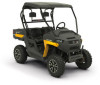
Cub Cadet Challenger 400 4x4 Operation Manual - Page 8
Occupant Protective Structure OPS M
 |
View all Cub Cadet Challenger 400 4x4 manuals
Add to My Manuals
Save this manual to your list of manuals |
Page 8 highlights
Ignition Switch (C) WARNING Never leave a running machine unattended. Always shift into park, stop engine and remove key to prevent unintended starting. The ignition switch is located to the right of the steering wheel. To start the engine, insert the key into the ignition switch and turn clockwise to the START position. Release the key into the RUN position once engine has started. To use the high beam feature, turn the key back to the high beam position. The high beam indicator in the instrument cluster will illuminate. See Figure 3-2 & Figure 3-3. Refer to Starting Engine section of this manual for detailed starting instructions. High Beam Position Seats (G) The driver's seat can be adjusted either forward or rearward. Push the adjustment handle to the right, slide the seat into the desired position and release the adjustment handle to lock the seat into place. See Figure 3-5. RUN Position START Position Figure 3-3 Gas Pedal (D) The gas pedal is located to the right of the brake pedal, beneath the dash panel. See Figure 3-1. Depressing the gas pedal will move the vehicle in the direction selected on the shift lever. As the pedal is slowly depressed, speed will continue to increase to the desired speed. Releasing the pedal will reduce the speed, but will not completely stop the vehicle. The brake must be applied to stop vehicle. Brake Pedal (E) The brake pedal is located to the left of the gas pedal, beneath the dash panel. See Figure 3-1. Remove foot from accelerator pedal and apply pressure to the brake pedal until vehicle slows down and stops. Seat Belts (F) The seat belts are located on the outside of the driver and passenger seats. Pull across your chest and lap and secure it to the seat belt latch located near the center console. Note: Seat belt warning indicator will flash for 8 seconds once the key is turned to the ON position to remind the operator and passenger to fasten their seat belt. WARNING Always wear the seat belt when operating the utility vehicle. The position of the lap belt portion of the seat belt should be positioned for both the operator and the passenger before driving. See Figure 3-4. Figure 3-5 Note: The passenger seat is not adjustable. Bed Tie-Down Rings (H) The bed tie-down rings can be used to secure items for transporting. Differential Lock Lever (I) The differential lock lever is located in the center console between the seats. When engaged, the differential lever locks the rear differential, giving equal power to both rear wheels. In addition, when the differential lock lever is in the ON position, the Differential Lock Indicator located in the instrument cluster will illuminate. See Figure 3-2. Shift Lever (J) The shift lever is located in the center console P between the seats and has four positions (PARK, REVERSE, NEUTRAL and DRIVE). The brake pedal must be fully depressed when moving the shift lever. One of the four gear R positions will be displayed in the instrument cluster. See Figure 3-2. N IMPORTANT: Never force the shift lever or attempt to shift while in motion. Doing so may result in serious damage to the utility vehicle's D transmission. 12V Power Outlet (K) The 12V power outlet is located on the right side of the dash panel. It is used for the convenience of plugging in accessories that require a power source with a maximum load of 7.5A at 12V. Figure 3-4 Auxiliary Switch Panel (L) The auxiliary switch panel is located on the right hand side of the dash panel above the handhold. When adding accessories requiring switches, use this area of the dash panel to install the desired switches. 2WD/4WD Switch The 2WD/4WD switch is located on the auxiliary switch panel and is used to switch between 2WD and 4WD. When the 4WD is activated the front wheels will highlight on the differential lock/4WD indicator. Occupant Protective Structure (OPS) (M) This utility vehicle is equipped with an Occupant Protective Structure (OPS) and seat belts. When used together they are effective in reducing crushing injuries to the operator and passenger in the event of an accidental rollover or tip-over. The safety provided by the OPS is minimized if the seat belt is not properly adjusted AND buckled. WARNING Always wear the seat belt when operating the utility vehicle. Use the following guidelines when using a utility vehicle equipped with OPS: 1. Be aware of overhead clearances in the area of operation. Check for clearance of door (or gate) openings and other overhead objects such as utility lines and tree branches. Overhead objects could catch the OPS and upset the utility vehicle. 2. Do not modify the OPS by drilling holes for, or welding accessories to the structure. 3. Do not use the OPS to pull objects with the utility vehicle. Use ONLY the utility vehicle hitch for pulling. 4. Do not operate the utility vehicle without the OPS and do not remove the OPS. 5. In the event of an accident, have the OPS carefully inspected and, if necessary, replaced by your Cub Cadet dealer. Do not attempt to repair the OPS. Cup Holders (N) The cup holders are located on top of the dash panel on both the left and right hand sides. WARNING Never operate this vehicle while under the influence of alcohol or drugs. Doing so can result in serious personal injury or death Cargo Bed (O) The cargo bed maximum capacity is 400 lbs. (181 kg), the passenger + operator max weight is 500 lbs. (226 kg), total cargo bed + passenger/operator weight is 900 lbs. (408 kg). The max towing weight is 1200 lbs. (544 kg) and the max tongue weight is 180 lbs. (81 kg). The cargo bed may be tilted for dumping loads. Push forward on the cargo bed latch lever to unlock the bed and manually lift the cargo bed. See Figure 3-1. Note: Access to the engine is achieved by raising the cargo bed. IMPORTANT: Do not exceed the vehicle's Total Payload Capacity of 900 lbs (408 kg), which includes driver, passenger, accessories, tongue load and cargo. Do not exceed 400 lbs. (181 kg) in the cargo bed. 8 Section 3- Controls & Operation
-
 1
1 -
2
-
 3
3 -
 4
4 -
 5
5 -
 6
6 -
 7
7 -
 8
8 -
 9
9 -
 10
10 -
 11
11 -
 12
12 -
 13
13 -
14
-
15
-
16
-
17
-
18
-
19
-
20
 |
 |
