Cub Cadet LTX 1045 LTX 1042 KW Operator's Manual - Page 13
Deck Lift Lever, Ignition Switch Module, Drive Pedal, Reverse Pedal, Cargo Net, Systems Indicator - battery
 |
View all Cub Cadet LTX 1045 manuals
Add to My Manuals
Save this manual to your list of manuals |
Page 13 highlights
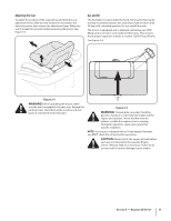
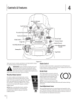
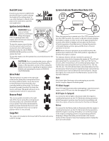
Deck Lift Lever Found on your tractor's right fender, the deck lift lever is used to change the height of the cutting deck. To use, move the lever to the left, then place in the notch best suited for your application. Ignition Switch Module WARNING! Never leave a running machine unattended. Always disengage PTO, set parking brake, stop engine and remove key to prevent unintended starting. To start the engine, insert the key into the ignition switch and turn clockwise to the START position. Release the key into the NORMAL MOWING MODE position once the engine has fired. To stop the engine, turn the ignition key counterclockwise to the STOP position. CAUTION: Prior to operating the tractor, refer to both Safety Interlock Switches and Starting The Engine in the Operation section of this manual for detailed instructions regarding the Ignition Switch Module and operating the tractor in REVERSE CAUTION MODE. Drive Pedal The drive pedal is located on the right side of the tractor, along the running board. Press the drive pedal forward to cause the tractor to travel forward. Ground speed is also controlled with the drive pedal. The further forward the pedal is pivoted, the faster the tractor will travel. The pedal will return to its original position when it's not pressed. Reverse Pedal The reverse pedal is located on the right side of the tractor along the running board. Ground speed is also controlled with the reverse pedal. The further downward the pedal is pivoted, the faster the tractor will travel. The pedal will return to its original position when it's not pressed. Cargo Net The cargo net is located on the lower half of the dash and can be used for storage. Systems Indicator Monitor/Hour Meter LCD When the ignition key is rotated out of the STOP position but not into the START position, the system's indicator monitor displays the battery's output, in volts, on its LCD for approximately five seconds, after which it displays an hour glass and the hours of tractor operation. Once the tractor is started, the monitor continually displays an hour glass and the hours of tractor operation on its LCD. NOTE: Hours of tractor operation are recorded any time the ignition key is rotated out of the STOP position, regardless of whether the engine is started. The Indicator Monitor will also remind the operator of maintenance intervals for changing the engine oil. The LCD will alternately flash the recorded hours, "CHG" and "OIL" for five minutes, after every 50 hours of recorded operation elapse. The maintenance interval lasts for two hours (from 50-52, 100-102, 150-152, etc.). The LCD will also flash as described above for five minutes every time the tractor's engine has been started during this maintenance interval. Before the interval expires, change the engine oil as instructed in the Maintenance section of this Operator's Manual. Brake If the Brake light illuminates when attempting to start the tractor's engine, depress the brake pedal. PTO (Blade Engage) If the PTO light illuminates when attempting to start the tractor's engine, move PTO lever into the disengaged (OFF) position. Oil (If Engine So Equipped) It is normal for the Oil light to illuminate while the engine is cranking during start-up, but if it illuminates during operation, while the engine is running, stop the tractor immediately and check the engine oil level as instructed in this Owner's Manual. Battery It is normal for the Battery light to illuminate while the engine is cranking during start-up, but if it illuminates during operation, while the engine is running, the battery is in need of a charge or the engine's charging system is not generating sufficient amperage. Charge the battery as instructed in the Service section of this manual or have the charging system checked by your Cub Cadet dealer. Section 4 - Controls & Features 13
-
 1
1 -
2
-
3
-
4
-
5
-
6
-
7
-
 8
8 -
 9
9 -
 10
10 -
 11
11 -
 12
12 -
 13
13 -
 14
14 -
 15
15 -
 16
16 -
 17
17 -
 18
18 -
19
-
20
-
21
-
22
-
23
-
24
-
25
-
26
-
27
-
28
-
29
-
30
-
31
-
32
-
33
-
34
-
35
-
36
-
37
-
38
-
39
-
40
-
41
-
42
-
43
-
44
-
45
-
46
-
47
-
48
-
49
-
50
-
51
-
52
-
53
-
54
-
55
-
56
-
57
-
58
-
59
-
60
-
61
-
62
-
63
-
64
-
65
-
66
-
67
-
68
-
69
-
70
-
71
-
72
 |
 |
