Cub Cadet LTX 1045 LTX 1042 KW Operator's Manual - Page 26
Cutting Blades - deck belt
 |
View all Cub Cadet LTX 1045 manuals
Add to My Manuals
Save this manual to your list of manuals |
Page 26 highlights
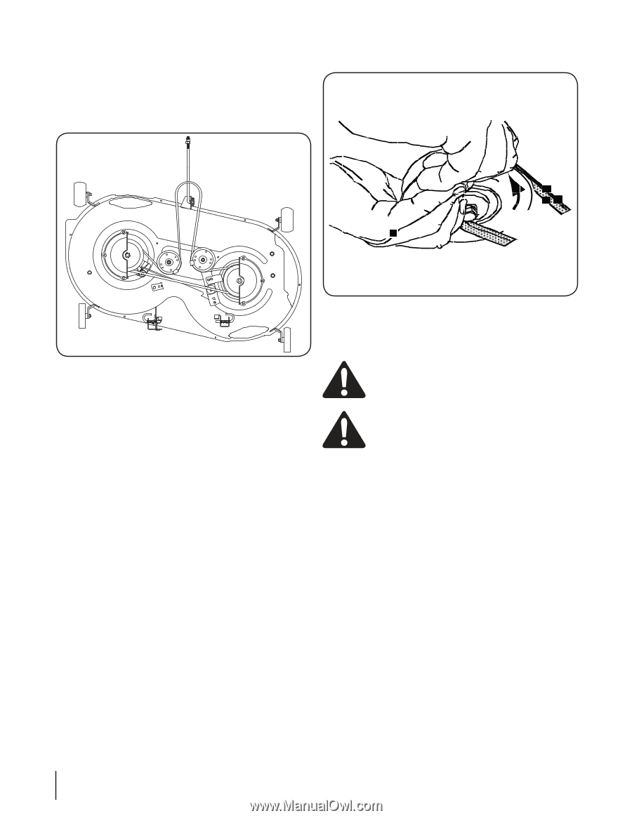
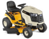
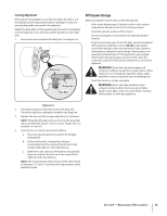
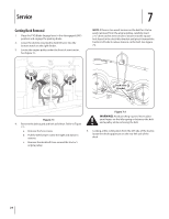
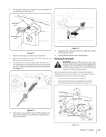
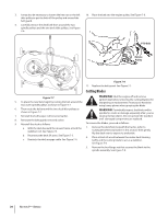
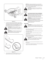
3. It may also be necessary to loosen the hex nut on the left idler pulley to get the belt off the pulley and around the belt guard. 4. Carefully remove the deck belt from around the two spindle pulleys and the two deck idler pulleys. See Figure 7-6. 10. Place the belt into the engine pulley. See Figure 7-8. PTO Belt Rotate Pulley Figure 7-8 11. Replace the belt guard. See Figure 7-1. Cutting Blades Figure 7-7 5. To place the new belt, begin by routing the belt around the two outer spindle pulleys as shown in Figure 7-7. WARNING! Shut the engine off and remove ignition key before removing the cutting blade(s) for sharpening or replacement. Protect your hands by using heavy gloves when grasping the blade 6. Then route the belt around the two deck idler pulleys as shown in Figure 7-7. WARNING! Periodically inspect the blade and/or spindle for cracks or damage, especially after you've 7. Reinstall the belt keeper rod loosened earlier. struck a foreign object. Do not operate the machine 8. Remount the belt guards removed earlier. until damaged components are replaced. 9. Reinstall the deck as follows: To remove the blades, proceed as follows: a. With the deck beneath the mower frame, attach the 1. Remove the deck from beneath the tractor, (refer to stabilizer rod. See Figure 7-5. Cutting Deck Removal earlier in this section) then gently flip the deck over to expose its underside. b. Reconnect the deck lift arms. See Figure 7-3. 2. Place a block of wood between the center deck housing c. Reattach the deck engage cable. See Figure 7-4. baffle and the cutting blade to act as a stabilizer. See Figure 7-9. 3. Remove the hex flange nut that secures the blade to the spindle assembly. See Figure 7-9. 26 Section 7- Service
-
 1
1 -
2
-
3
-
4
-
5
-
6
-
7
-
8
-
9
-
10
-
11
-
12
-
13
-
14
-
15
-
16
-
17
-
18
-
19
-
20
-
 21
21 -
 22
22 -
 23
23 -
 24
24 -
 25
25 -
 26
26 -
 27
27 -
 28
28 -
 29
29 -
 30
30 -
 31
31 -
32
-
33
-
34
-
35
-
36
-
37
-
38
-
39
-
40
-
41
-
42
-
43
-
44
-
45
-
46
-
47
-
48
-
49
-
50
-
51
-
52
-
53
-
54
-
55
-
56
-
57
-
58
-
59
-
60
-
61
-
62
-
63
-
64
-
65
-
66
-
67
-
68
-
69
-
70
-
71
-
72
 |
 |