Cub Cadet LTX 1050 KH LTX 1046 KW Operator's Manual - Page 25
Cutting Blades
 |
View all Cub Cadet LTX 1050 KH manuals
Add to My Manuals
Save this manual to your list of manuals |
Page 25 highlights
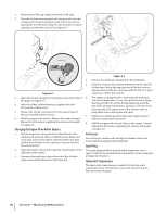
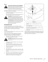
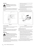
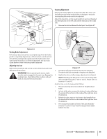
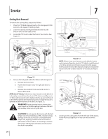
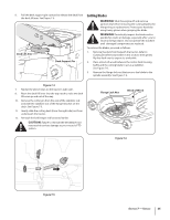
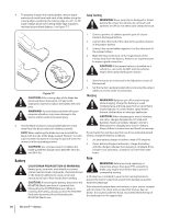
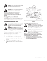
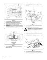
6. Pull the deck support pin outward to release the deck from the deck lift arm. See Figure 7-4. Deck Lift Arm Deck Support Pin Cutting Blades WARNING! Shut the engine off and remove ignition key before removing the cutting blade(s) for sharpening or replacement. Protect your hands by using heavy gloves when grasping the blade WARNING! Periodically inspect the blade and/or spindle for cracks or damage, especially after you've struck a foreign object. Do not operate the machine until damaged components are replaced. To remove the blades, proceed as follows. 1. Remove the deck from beneath the tractor, (refer to Cutting Deck Removal earlier in this section) then gently flip the deck over to expose its underside. 2. Place a block of wood between the center deck housing baffle and the cutting blade to act as a stabilizer. See Figure 7-6. 3. Remove the flange lock nut that secures the blade to the spindle assembly. See Figure 7-6. Figure 7-4 7. Repeat the above steps on the tractor's right side. 8. Move the deck lift lever into the top notch to raise the deck lift arms up and out of the way. 10. Remove the cotter pin from the end of the stabilizer rod and slide the stabilizer out of the hanger bracket on the deck. See Figure 7-5. 11. Gently slide the cutting deck (from the right side) out from underneath the tractor. 12. Reinstall the belt keeper rod loosened earlier. CAUTION: Failure to reinstall the belt keeper rod may result in serious damage to your tractor's PTO system. Flange Lock Nut Block of Wood Figure 7-6 Figure 7-5 Section 7 - Service 25
-
 1
1 -
2
-
3
-
4
-
5
-
6
-
7
-
8
-
9
-
10
-
11
-
12
-
13
-
14
-
15
-
16
-
17
-
18
-
19
-
 20
20 -
 21
21 -
 22
22 -
 23
23 -
 24
24 -
 25
25 -
 26
26 -
 27
27 -
 28
28 -
 29
29 -
 30
30 -
31
-
32
-
33
-
34
-
35
-
36
-
37
-
38
-
39
-
40
-
41
-
42
-
43
-
44
-
45
-
46
-
47
-
48
-
49
-
50
-
51
-
52
-
53
-
54
-
55
-
56
-
57
-
58
-
59
-
60
-
61
-
62
-
63
-
64
-
65
-
66
-
67
-
68
-
69
-
70
-
71
-
72
 |
 |
