Cub Cadet PRO X 636 Operation Manual - Page 25
Servicing Electrical System, Safety Interlock System & Switch Operation Checks, Rear Tire
 |
View all Cub Cadet PRO X 636 manuals
Add to My Manuals
Save this manual to your list of manuals |
Page 25 highlights
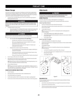
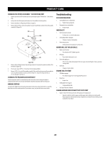
PRODUCT CARE SERVICING ELECTRICAL SYSTEM Fuse The 25 amp fuse holder is located on the right side of the mower frame under the control panel. The fuse is a standard plug-in type automotive fuse. Always use the same capacity fuse for replacement. Check the 25 amp fuse for any electrical problems. If you have a recurring problem with blown fuses, have the mower's electrical system checked by your Cub Cadet Service Dealer. SAFETY INTERLOCK SYSTEM & SWITCH OPERATION CHECKS The following operational checks should be made daily with the mower on a flat surface and the wheels blocked to prevent unintentional movement of the mower: PTO Switch 1. Stand on the operator's platform. With the drive control levers in the neutral position and the parking brake engaged, engage the PTO switch by pulling up on the knob and try to start the engine. The engine should not start. If it does, the PTO switch must be replaced. See your Cub Cadet Service Dealer. 2. If the engine does not start, disengage the PTO by pressing the knob down and start the engine. Now engage the PTO and the blades should rotate. 3. If the blades do not turn, the PTO switch must be replaced, the platform switch must be replaced or the electric PTO clutch must be repaired. See your Cub Cadet Service Dealer. Parking Brake Switch 1. Stand on the operator's platform. With the drive control levers in the neutral position and the PTO disengaged, release the parking brake and try to start the engine. The engine should not start. 2. If it does, the parking brake switch must be repositioned or replaced. See your Cub Cadet Service Dealer. If the engine does not start, engage the parking brake and start the engine. Operator's Presence Control Switch 1. With the drive control levers in the neutral position, the parking brake engaged and the PTO disengaged, start the engine. Disengage the parking brake and step off of the operator's platform. The engine should stop. 2. If the engine does not stop, the operator's platform switch must be replaced. See your Cub Cadet Service Dealer. 3. With the drive control levers in the neutral position, the parking brake engaged and the PTO disengaged, stand on the operator's platform and start the engine. Engage the PTO and the blades should start to rotate. Step off of the operator's platform and the blades should stop. 4. If the blades do not stop when you step off of the operator's platform, the operator's platform switch must be replaced. See your Cub Cadet Service Dealer. Electric PTO Clutch This clutch operates when the engine is running, the operator is on the operator's platform and the PTO is engaged. This electric clutch is a normally trouble free device. If a problem develops and the blades do not turn first check the 25 amp fuse, then investigate the wiring harness and the connections to the platform switch, the PTO switch and the electric blade clutch. Then check the operator's platform switch, the PTO switch and finally the electric blade clutch. If the PTO clutch is still not working properly, see an authorized service dealer. REAR TIRE REMOVAL 1. With the tires on the ground, loosen, but do not remove the four lug nuts (a) (Figure 27). 2. Elevate the mower so tire is off the ground. 3. Remove the four lug nuts to remove tire from mower. 4. With the mower elevated, use the four lug nuts to reinstall the tire onto the mower. Hand tighten lug nuts. 5. Lower the mower so tire is on the ground. 6. Torque the lug nuts (a) to 65-70 ft-lbs (88.13-94.91 N-m). in a crisscross pattern. (a) DECK REMOVAL Figure 27 WARNING The muffler and any surrounding parts at the rear of the mower may be extremely hot, and could cause serious burns. Use extreme caution when near the muffler. Allow the muffler to fully cool before removing the belt from the PTO pulley. Remove the mower deck from the mower as follows: 1. Lower the deck to the ground. Capture the deck lift by placing the clevis pin behind the lowest position. 2. Apply the parking brake. Remove ignition key and the spark plug cap. 3. Using a 1⁄2" (12.7 mm) drive in the idler pulley bracket (a), turn the wrench towards the front of the mower and slide the PTO belt (b) off the deck pulleys (c) and the PTO clutch (d) (Figure 28). 48, 54 and 60 Inch Decks (c) (a) (b) (c) (b) (d) 36 Inch Decks (c) (c) (c) (a) (c) (a) (b) (b) (c) (d) (c) Figure 28 4. Remove the four lynch pins (e) that secure the deck to the deck lift assembly (Figure 29). 5. Remove the lynch pin (f) securing the rear stabilizer bar to the rear, right side of the deck. (Figure 29). 25
-
 1
1 -
2
-
3
-
4
-
5
-
6
-
7
-
8
-
9
-
10
-
11
-
12
-
13
-
14
-
15
-
16
-
17
-
18
-
19
-
 20
20 -
 21
21 -
 22
22 -
 23
23 -
 24
24 -
 25
25 -
 26
26 -
 27
27 -
 28
28 -
 29
29 -
 30
30 -
31
-
32
 |
 |
