Cub Cadet PRO X 636 Operation Manual - Page 8
Assembly
 |
View all Cub Cadet PRO X 636 manuals
Add to My Manuals
Save this manual to your list of manuals |
Page 8 highlights
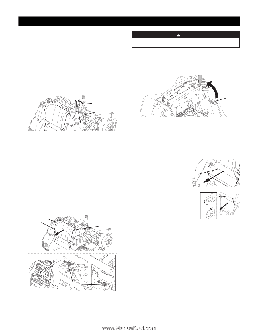
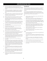
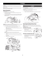
ASSEMBLY IMPORTANT: This mower is shipped without gasoline in the engine. Be certain to service engine with gasoline and check oil as instructed in the Operation section of the Engine Manual before starting or operating your mower. NOTE: References to LEFT, RIGHT, FRONT, and REAR indicate that position on the mower when facing forward while standing on the operator's platform. Mower Preparation TOOLS NEEDED: Safety glasses, leather gloves, wire cutters. 1. Remove the upper crating material from the shipping pallet, and cut any bands or tie straps securing the mower to the pallet. 2. Use the deck lift handle (a) to raise the deck to the transport lock position (b) (highest adjustment setting) and insert the clevis pin (c) into the highest mowing setting (d) to secure the deck lift handle in place (Figure 1). (a) (d) WARNING Do not tow the mower, even with the bypass valves engaged. Serious transmission damage will result from doing so. 4. Carefully roll the mower off the shipping pallet. IMPORTANT: The bypass valves MUST be closed before operating the mower. 5. Reverse STEP 3 to close the two bypass valves. 6. To engage the parking brake, pull back completely on the parking brake lever (j) (Figure 3). (j) (b) (c) Figure 1 IMPORTANT: The mower is equipped with two hydrostatic transmissions. Each transmission is equipped with a bypass valve that MUST be opened before manually moving the mower. 3. Perform the following to open the two hydrostatic transmission bypass valves (Figure 2): a. Loosen the two star knobs (e) securing the leg pad (f) to the mower. NOTE: Leg pad for mowers with 48, 56 or 60 inch decks shown. Leg pad for mowers with 36 inch deck adjusts the same. b. Remove the leg pad from the mower. c. Remove the rear panel from the mower. Refer to Removing/Installing The Rear Panel on page 8. IMPORTANT: DO NOT open the bypass valves more than a maximum of two turns. d. Locate the hydrostatic transmissions and open the two bypass valves (i) a maximum of two turns. e. Reinstall the rear panel. Refer to Removing/Installing The Rear PanelRear Panel with star knobs on page 8. f. Using the two star knobs, reinstall the leg pad. (e) (f) (e) Figure 3 7. Cut any wire ties holding the chute deflector up and discard any packing material. Removing/Installing The Rear Panel NOTE: The rear panel is secured to the mower using two star knobs or two quarter turn latches. IMPORTANT: Ensure the mower is unoccupied with the engine off and parking break engaged before performing this procedure. REAR PANEL WITH STAR KNOBS 1. Remove the two star knobs (a) securing the rear (a) panel (b) to the mower . 2. Remove the rear panel from the mower. (b) 3. Reverse STEPS 1 - 2 to install the rear panel. REAR PANEL WITH QUARTER TURN LATCHES 1 1. Lift latch up and rotate the latch one 1/4 turn and align the latch with the slot in the rear panel. Repeat this step to the remaining latch. 2 2. Remove the rear panel from the mower. 3. Reverse STEPS 1 - 2 to install the rear panel. (a) (b) (i) Figure 2 8
-
 1
1 -
2
-
 3
3 -
 4
4 -
 5
5 -
 6
6 -
 7
7 -
 8
8 -
 9
9 -
 10
10 -
 11
11 -
 12
12 -
 13
13 -
14
-
15
-
16
-
17
-
18
-
19
-
20
-
21
-
22
-
23
-
24
-
25
-
26
-
27
-
28
-
29
-
30
-
31
-
32
 |
 |