Cub Cadet Pro Z 160L EFI Owners Manual - Page 20
Adjustments
 |
View all Cub Cadet Pro Z 160L EFI manuals
Add to My Manuals
Save this manual to your list of manuals |
Page 20 highlights
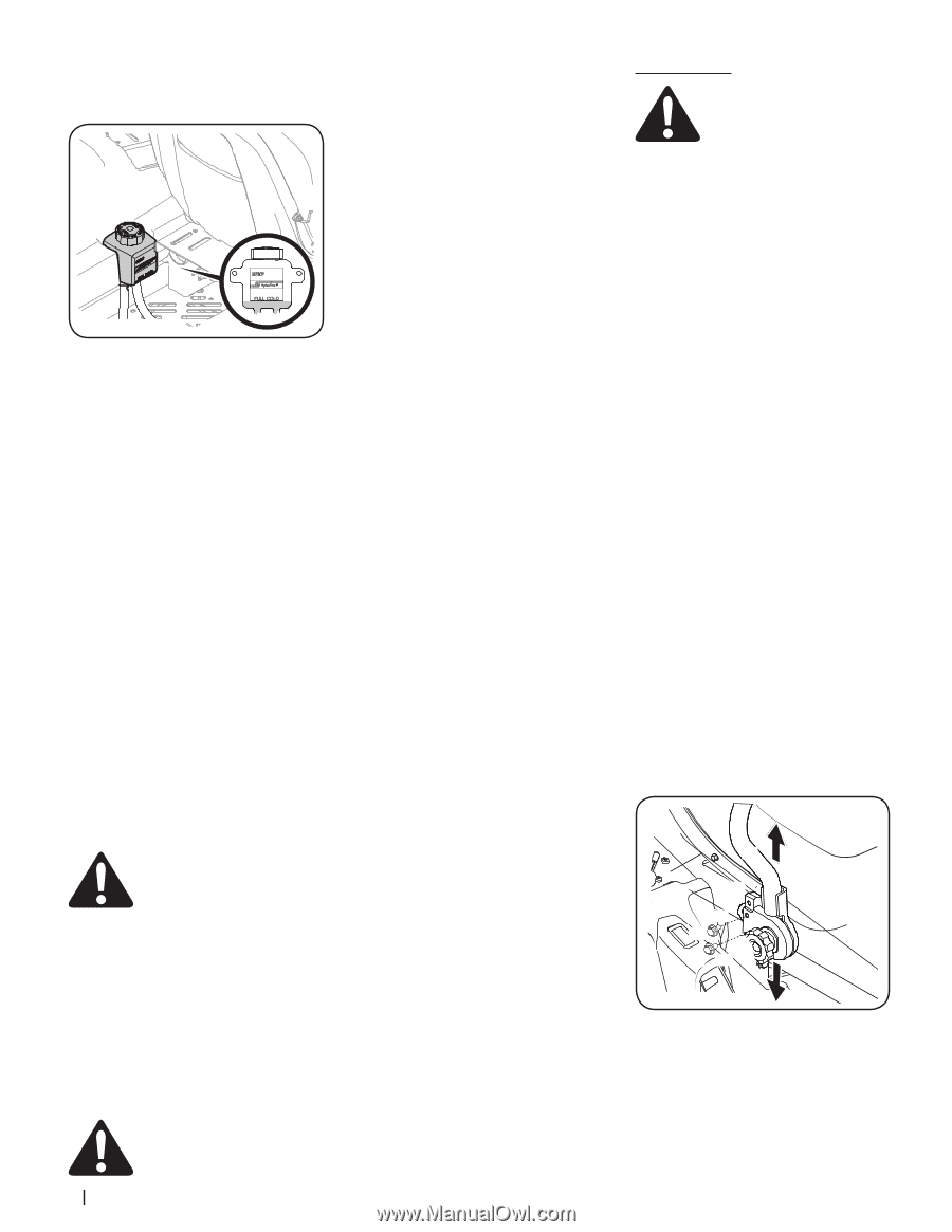
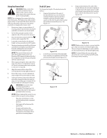
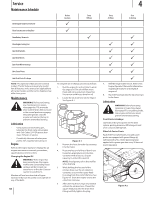
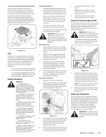
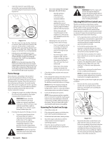
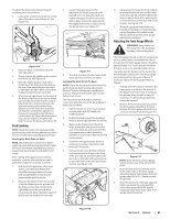
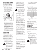
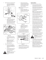
1. Clean the reservoir cap and the area around the cap to prevent debris from contaminating the transmission oil. See Figure 4-6. Figure 4-6 2. Turn the reservoir cap counter-clockwise to remove, then check the oil level in the reservoir. Oil should be visible at the bottom of the cup, but the oil level must NOT be above the "FULL COLD" line. See Figure 4-6. DO NOT FILL THE RESERVOIR. 3. If necessary to add oil because of some type of leakage, use a quality 20W50 motor oil and add only enough oil to bring the level to the "FULL COLD" line. Reinstall the cap and fully tighten. NOTE: Prior to the initial operation of the tractor, the oil level in the reservoir may be slightly higher than the maximum due to air in the oil lines. Operation of the tractor will eventually purge the air from the lines and the oil level will settle to the maximum. Tractor Storage If your tractor is not going to be operated for an extended period of time (30 days to approximately six months), the tractor should be prepared for storage. Store the tractor in a dry and protected location. If stored outside, cover the tractor (including the tires) to protect it from the elements. The procedures outlined below should be performed whenever the tractor is placed in storage. 1. Change the engine oil and filter following the instructions provided in the engine manual packed with this manual. WARNING! Never store the tractor with fuel in the tank indoors or in poorly ventilated enclosures, where fuel fumes may reach an open flame, spark or pilot light as on a furnace, water heater, clothes dryer, etc. 2. If storing the tractor for 30 days or more: a. To prevent gum deposits from forming inside the engine's carburetor and causing possible malfunction of the engine, the fuel system must be either completely emptied, or the gasoline must be treated with a stabilizer to prevent deterioration. WARNING! Fuel left in the fuel tank deteriorates and will cause serious starting problems. 20 Section 4- Service b. Use a fuel stabilizer for storage between 30 and 90 days: • Read the product manufacturer's instructions and recommendations. • Add to clean, fresh gasoline the correct amount of stabilizer for the capacity (approximately 3 gallons) of the fuel system. • Fill the fuel tank with treated fuel and run the engine for 2-3 minutes to get stabilized fuel into the carburetor. c. Emptying the fuel system for storage of more than 90 days: • Prior to putting the tractor in storage, monitor fuel consumption with the goal of running the fuel tank empty. • Run the engine until it begins to stall. Use the choke to keep the engine running until all fuel in the carburetor has been exhausted. • Referring to the engine manual, drain the fuel from the carburetor bowl. 3. Clean the engine and the entire tractor thoroughly. 4. Fully charge the battery, then disconnect the negative cable at the battery to prevent possible discharge. Recharge the battery periodically when in storage. NOTE: Remove the battery if exposed to prolonged periods of sub-freezing temperatures. Store in a cool, dry location where temperatures are above freezing. 5. Lubricate all lubrication points. NOTE: Using a pressure washer or garden hose is not recommended for cleaning your tractor. It may cause damage to electrical components, spindles, pulleys, bearings or the engine. The use of water will result in shortened life and reduce serviceability. Removing The Tractor From Storage 1. Check the engine oil. 2. Fully charge the battery and inflate the tires to the recommended pressure. 3. Fill the fuel tank with clean, fresh gasoline. 4. Start the engine and allow to idle for a few minutes to ensure engine is operating properly. 5. Drive the tractor without a load to make certain all the tractor systems are functioning properly. Adjustments WARNING! Shut the engine off, remove the ignition key and engage the parking brake before making adjustments. Protect your hands by using heavy gloves when handling the blades. Adjusting RH & LH Drive Control Levers The RH and LH drive control levers can be adjusted up or down and forward or backward for the comfort of the operator. The drive control levers can be placed in either of two height positions, and/or can be moved forward or rearward. Proper drive control lever and seat adjustment will result in the following: 1. In the neutral position with hands on the control levers, the operator's upper arms should be relaxed and approximately vertical and their forearms should be approximately horizontal. 2. In the full forward position, the operator's back should stay in contact with the seat back and the control levers should not contact operator's legs. 3. In the full reverse position, the control levers should not contact the operator's legs or torso. 4. Set the seat to the preferred operating position. The adjustment lever is located under the front edge of the seat. The seat has 5" of front-to-rear adjustment available. 5. Check factory settings of control levers for the conditions listed above. NOTE: If control lever adjustments are required, height adjustments should be made prior to angular adjustments. To adjust the drive control lever height, proceed as follows: 1. Remove the hex screws (a) and flat washers (b) securing the drive control lever (c) to the lower arm assembly (d). Refer to Figure 4-7. (c) (d) (b) (a) (a) (b) Figure 4-7 2. Reposition the drive control lever (c) to align with the other set of holes in the lower arm assembly (d) and insert the hex screws (a) through the flat washers (b) and then the drive control lever (c) then into the lower arm assembly (d). Tighten the hex screws (a) until snug. Repeat the steps on the other control arm.
-
 1
1 -
2
-
3
-
4
-
5
-
6
-
7
-
8
-
9
-
10
-
11
-
12
-
13
-
14
-
 15
15 -
 16
16 -
 17
17 -
 18
18 -
 19
19 -
 20
20 -
 21
21 -
 22
22 -
 23
23 -
 24
24 -
 25
25 -
26
-
27
-
28
-
29
-
30
-
31
-
32
 |
 |