Cub Cadet Pro Z 160L EFI Owners Manual - Page 9
Assembly & Set-Up - reviews
 |
View all Cub Cadet Pro Z 160L EFI manuals
Add to My Manuals
Save this manual to your list of manuals |
Page 9 highlights
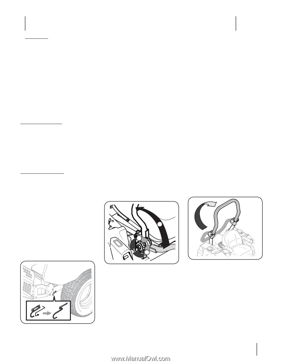
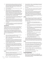
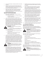
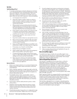
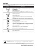
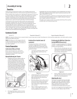
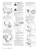
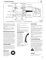
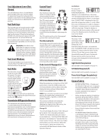
Assembly & Set-Up Thank You Thank you for purchasing this product. It was carefully engineered to provide excellent performance when properly operated and maintained. Please read this entire manual prior to operating the equipment. It instructs you how to safely and easily set up, operate and maintain your machine. Please be sure that you, and any other persons who will operate the machine, carefully follow the recommended safety practices at all times. Failure to do so could result in personal injury or property damage. All information in this manual is relative to the most recent product information available at the time. Review this manual frequently to familiarize yourself with the machine, its features and operation. Please be aware that this Operator's Manual may cover a range of product specifications for various models. Characteristics and features discussed and/or illustrated in this manual may not be applicable to all models. We reserve the right to change product specifications, designs and equipment without notice and without incurring obligation. 2 If applicable, the power testing information used to establish the power rating of the engine equipped on this machine can be found at www.opei.org or the engine manufacturer's web site. If you have any problems or questions concerning the machine, phone your local authorized service dealer or contact us directly. We want to ensure your complete satisfaction at all times. Throughout this manual, all references to right and left side of the machine are observed from the operating position. Contents of Carton • Tractor (1) • Operator's Manual (1) • Engine Operator's Manual (1) NOTE: This Operator's Manual covers several models. Features may vary by model. Not all features in this manual are applicable to all models and the model depicted may differ from yours. NOTE: All references in this manual to the left or right side and front or back of the tractor are from the operating position only. Exceptions, if any, will be specified. Tractor Preparation Lubrication & Grease Points Before operating the tractor, refer to the Service section of this manual to check the Lubrication & Grease Points. Grease and lubricate if necessary. Position Drive Control Levers (if necessary) The drive control levers of the tractor are lowered for shipping purposes. The levers must be repositioned to operate the tractor. To reposition the control levers for operation, proceed as follows: 1. Loosen the control lever knobs on the side of the drive control levers. See Figure 2-2. Positioning the Roll Over Protective System (ROPS) (If necessary) The ROPS is shipped folded down for shipping purposes. To place the ROPS into the operation position proceed as follows. 1. Remove the left and right clevis pins and cotter pins securing the ROPS in position and rotate it so that they allow the ROPS to move freely. See Figure 2-3. Manually Moving the Tractor 1. Engage the transmission bypass rods, one on each side of the tractor, to move the tractor manually without starting it. The transmission bypass rods are located on the rear of the tractor, just inside each rear wheel. Place the lapbars in the neutral (fully inward) position to disengage the parking brake. Engage the bypass rods by pulling each one back (a) and hooking it into the slot (b) to lock it into place. See Figure 2-1. 2 2 1 a b Figure 2-1 2. Disengage the bypass rods by reversing steps a & b after moving the tractor. See Figure 2-1. Figure 2-2 2. Lift and swing that control lever upward into the desired position and secure in place by tightening the control lever knob. See Figure 2-2. 3. Note the relative position of the control lever to the pivot bracket, then repeat the previous steps to reposition the other control lever in approximately the same position. 4. Refer to "Adjusting the Drive Control Levers" on page 20 for instructions on the final adjustment of the levers. Figure 2-3 2. Rotate to ROPS forward and re-insert the clevis pins and cotter pins to secure the ROPS in the operating position. Adjusting the Seat This tractor is equipped with an adjustable seat, which includes a retractable seat belt assembly and an Operator Presence Sensor (OPS). The OPS in the form of a switch, is integrated into the seat bottom and is connected to the machine electrical system. The seat can be adjusted forward and back and the arm rest can be adjusted up and down. 9
-
 1
1 -
2
-
3
-
 4
4 -
 5
5 -
 6
6 -
 7
7 -
 8
8 -
 9
9 -
 10
10 -
 11
11 -
 12
12 -
 13
13 -
 14
14 -
15
-
16
-
17
-
18
-
19
-
20
-
21
-
22
-
23
-
24
-
25
-
26
-
27
-
28
-
29
-
30
-
31
-
32
 |
 |