Cub Cadet RZT SX 54 Operation Manual - Page 9
Air Filter Service
 |
View all Cub Cadet RZT SX 54 manuals
Add to My Manuals
Save this manual to your list of manuals |
Page 9 highlights
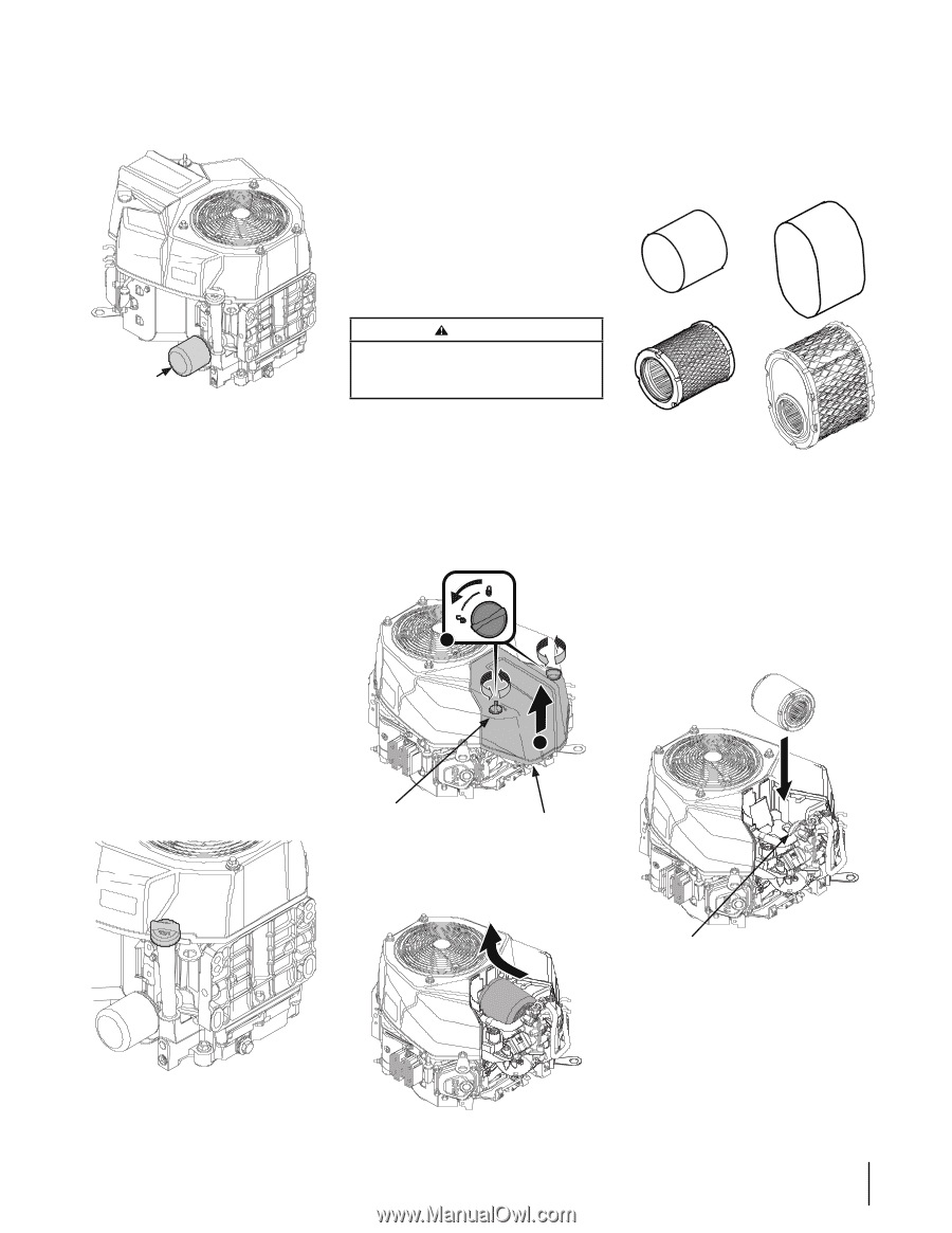
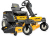
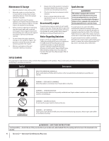
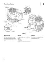
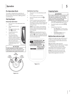
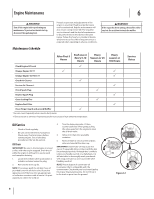
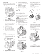
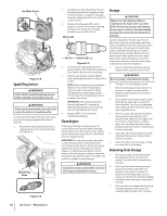
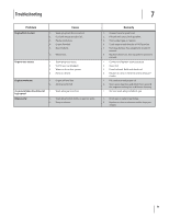
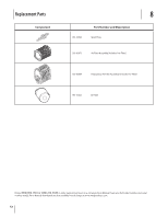
Replace Oil Filter This engine is equipped with a spin-on oil filter that should be replaced each time an oil change is performed, every season or 100 hours. Refer to Figure 6-2. 3. Pour oil into the dipstick tube. Do not over fill. With an oil filter change the high level amount of oil for this engine is 1900 ml (64.25 fl. oz.). 4. Install dipstick and turn to locked position before starting engine. 5. Start engine. Allow to run for a few seconds and then shut down the engine. 6. Check the oil level. See Checking Oil Level section. Air Filter Service Paper filters cannot be cleaned and should be replaced every 100 operating hours; more often if used in extremely dusty conditions. 4. Remove the foam pre-filter from around the paper air filter. See Figure 6-6. Replace paper element when dirty or damaged. Clean foam element or replace when damaged. NOTE: The foam element cannot be purchased separately. Air filter is only sold as an assembly. Pre-Filter Pre-Filter WARNING! Oil Filter Never use gasoline or low flash point solvents for cleaning the air filter element. A fire or explosion could result. Figure 6-2 1. Drain oil. See oil drain section. IMPORTANT: Never run the engine without the air filter. Rapid engine wear will result. 2. Remove oil filter. Dispose of old oil filter NOTE: Standard air filter and cover shown in properly. Figures 6-4, 6-5 and 6-7. Heavy duty air filter and cover is serviced the same way. 3. Lube gasket of new oil filter with clean oil. 1. Unscrew a 1/4 turn to unlock the thumb 4. Install and turn oil filter by hand until the screws. 5. gasket comes in contact with the sealing surface of the crankcase cover, then 2. Remove the air filter cover. See Figure tighten the oil filter, 10-12 Nm (88.5-106.2 6-4. in-lb), 1/2-3/4 turn. 5. Add oil. See add oil section. 6. Make sure dipstick is installed. 6. 7. Start and run engine. Check for leaks. 1 8. Stop engine. Wait a few minutes and check the oil level. See checking oil level section. 9. Install and tighten dipstick. Add Oil IMPORTANT: Be sure to check engine on a level surface with the engine stopped. 1. Wipe around dipstick cap and tube with a clean cloth to remove any debris. See Figure 6-3. Thumb Screw 2 Air Filter Cover Air FIlter Heavy Duty Air FIlter Figure 6-6 To clean foam element, wash in a mild liquid detergent and water. Squeeze or press the foam element to rinse out dirt and water. Do not twist; this could damage or tear the foam element. Allow to dry thoroughly before using. DO NOT oil the foam element. Attach the new air filter with foam element, aligning the hole in the air filter with the intake manifold. See Figure 6-7. Figure 6-4 3. Pull up on an angle and then forward to remove the air filter. See Figure 6-5. Intake Manifold Figure 6-7 7. Attach the air filter cover. See Figure 6-8. Turn thumb screws clockwise a 1/4 turn until snug. Check for any misalignment. Figure 6-3 2. Remove dipstick and wipe clean with a cloth. Figure 6-5 Section 6 - Maintenance 9
-
 1
1 -
2
-
3
-
 4
4 -
 5
5 -
 6
6 -
 7
7 -
 8
8 -
 9
9 -
 10
10 -
 11
11 -
 12
12 -
 13
13 -
 14
14 -
15
-
16
-
17
-
18
-
19
-
20
-
21
-
22
-
23
-
24
 |
 |