Cub Cadet SC 300 Operation Manual - Page 9
Cub Cadet SC 300 Manual
 |
View all Cub Cadet SC 300 manuals
Add to My Manuals
Save this manual to your list of manuals |
Page 9 highlights
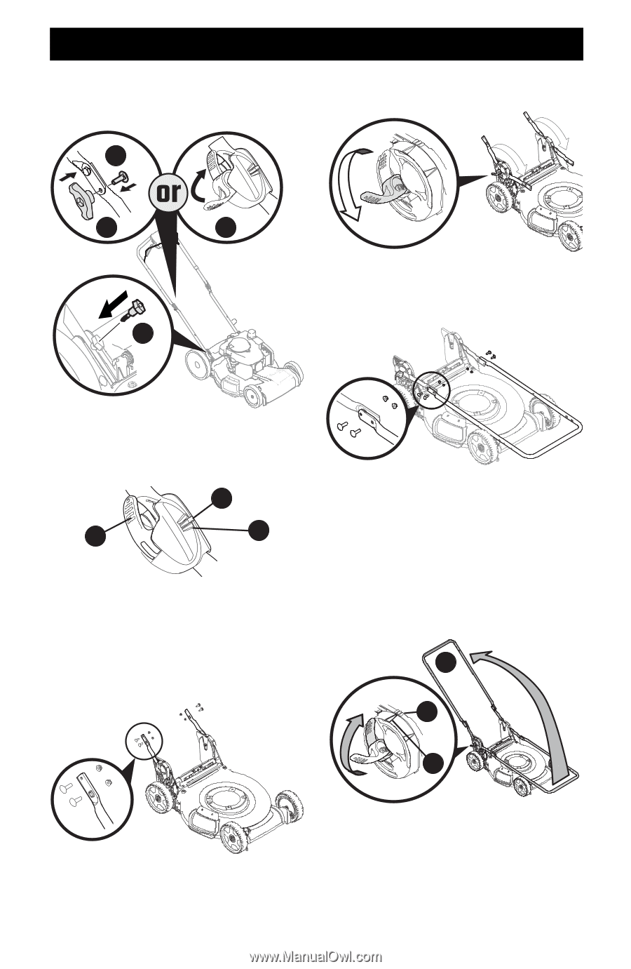
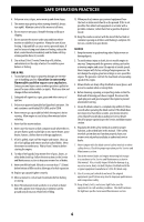
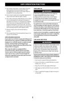
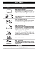
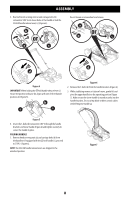
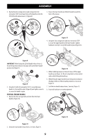
ASSEMBLY 4. Reattach knobs or wing nuts (a) and carriage bolts (b) removed in STEP 2 into lower holes of the handle or lock the EZ-fold handle release levers (c) (Figure 8). 3. Ensure the lower handles are folded forward towards the front of the mower. b a c d Figure 11 4. Using the four carriage bolts and nuts removed in STEP 2, secure the upper handle to the lower handle. Tighten hardware securely to secure the handle in place (Figure 12). Figure 8 IMPORTANT: When locking the EZ-fold handle release lever (c) ensure the position indicator (e) aligns with one of three handle positions (f) (Figure 9). e c f Figure 9 5. Using the T-bolts (d) removed in STEP 2, secure the lower handle to the handle brackets (Figure 8) and tighten securely to secure the handle in place. VERTICAL STORAGE HANDLE 1. Remove the four carriage bolts and nuts from the lower handles (Figure 10). Figure 12 5. While stabilizing mower so it doesn't move, lift the upper handle up (a) (Figure 13). Do not crimp blade or drive control cables while lifting the handle up. 6. When lifting the upper handle ensure the position indicator (b) aligns with one of three handle positions (c). See inset, Figure 13. 7. Lock the two handle release levers. See inset, Figure 13. 8. Ensure all hardware is securely tightened. a c b Figure 13 Figure 10 2. Unlock the two handle release levers. See inset, Figure 11. 9
-
 1
1 -
2
-
3
-
 4
4 -
 5
5 -
 6
6 -
 7
7 -
 8
8 -
 9
9 -
 10
10 -
 11
11 -
 12
12 -
 13
13 -
 14
14 -
15
-
16
-
17
-
18
-
19
-
20
-
21
-
22
-
23
-
24
-
25
-
26
-
27
-
28
-
29
-
30
-
31
-
32
-
33
-
34
-
35
-
36
-
37
-
38
-
39
-
40
-
41
-
42
-
43
-
44
-
45
-
46
-
47
-
48
-
49
-
50
-
51
-
52
-
53
-
54
-
55
-
56
-
57
-
58
-
59
-
60
-
61
-
62
-
63
-
64
-
65
-
66
-
67
-
68
-
69
-
70
-
71
-
72
 |
 |