Cub Cadet ZTX6 54 Operation Manual - Page 10
Operation
 |
View all Cub Cadet ZTX6 54 manuals
Add to My Manuals
Save this manual to your list of manuals |
Page 10 highlights
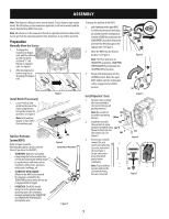
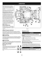
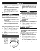
OPERATION Note: This Operator's Manual covers several models. Tractor features may vary by model. Not all features in this manual are applicable to all tractor models and the tractor depicted may differ from yours. Note: References to LEFT, RIGHT, FRONT, and REAR indicate that position on the tractor when facing forward while seated in the operator's seat. 1 Lapbar Drive Control Levers The RH (Right Hand) and LH (Left Hand) lapbar drive control levers are located on each side of the operator's seat. The hinged levers pivot outward to permit the operator to sit in the seat, or dismount. To start the tractors engine, the lapbar drive control levers must be fully out and in park position. When the lapbar drive control levers are fully outward, the parking brake is engaged. Each drive control lever controls the respective transmission. Consequently, these levers control all of the tractors movement. Driving and steering using these control levers is quite different from a conventional tractor and will take practice to master. Refer to Practice Operation section for further instructions. 2 Deck Height Index Each rotation represents a 6.35 mm) change in deck height. Positions range from 1" (2.5 cm) to 4-¾" (12 cm) at the highest point. See 4a and 4b in Figure 16. 7 7 15 3 Deck Transport Lock Control The deck lift handle is used to lock the deck above its highest cut setting into transport mode. To engage the deck transport lock control depress the deck lift pedal and move the knob into its rear position. To disengage the transport lock and set the deck to its designated cut height, depress the deck lift pedal and move the knob into its front position. 4a Deck Lift Pedal The deck lift pedal is located on the front, right corner of the platform. The pedal is used in conjunction with the deck lift knob to raise and lower the mowing deck. Push forward on the deck lift pedal, rotate the deck lift knob to the desired height and release the deck lift pedal. 4b Deck Lift Knob The deck lift knob is used in conjunction with the deck lift pedal to raise and lower the mowing deck. Push forward on the deck lift pedal, rotate the deck lift knob to the desired height and release the deck lift pedal. 5 Power Take-Off (PTO) Electric PTO The PTO switch operates the electric PTO clutch mounted on the bottom of the engine crankshaft. Pull the switch knob upward to engage the PTO clutch, or push the knob downward to disengage the clutch. The PTO switch must be in the "OFF" position when starting the engine. 9 10 11 1 12 86 5 2 3 4a 4b 13 Figure 16 6 Ignition Switch WARNING Never leave a running machine unattended. Always disengage PTO, set parking brake, stop engine and remove key to prevent unintended starting. The ignition switch has three positions: STOP - The engine and electrical system is turned off. RUN - The riding mower electrical system is energized. START - The starter motor will turn over the engine. Release the key immediately when the engine starts. Note: To prevent accidental starting and/or battery discharge, remove key from the ignition switch when tractor is not in use. 7 Transmission Bypass Rods The transmission bypass rods (one for each RH and LH transmission) are located on the rear of the tractor, next to the engine.When engaged, the two rods open a bypass within the hydrostatic transmissions, which allows the tractor to be pushed short distances by hand. Refer to the Assembly section for additional instructions. CAUTION Never tow your tractor. Towing the tractor with the rear wheels on the ground may cause severe damage to the transmissions. 10
-
 1
1 -
2
-
3
-
4
-
 5
5 -
 6
6 -
 7
7 -
 8
8 -
 9
9 -
 10
10 -
 11
11 -
 12
12 -
 13
13 -
 14
14 -
 15
15 -
16
-
17
-
18
-
19
-
20
-
21
-
22
-
23
-
24
-
25
-
26
-
27
-
28
-
29
-
30
-
31
-
32
-
33
-
34
-
35
-
36
-
37
-
38
-
39
-
40
-
41
-
42
-
43
-
44
-
45
-
46
-
47
-
48
 |
 |
